Control installation – Bell & Gossett P86272B VS Variable Speed Pump Control User Manual
Page 5
5
CONTROL INSTALLATION
MOUNTING THE CONTROL
• The VS is designed to mount on a standard 4"x4" electrical
box.
• Locate the VS in a convenient location near the variable
speed pump. The VS can not be mounted more than 500'
from any sensor location.
• Mount the VS away from excessive heat or cold. Ambient
operating temperature is from 20° to 120°F.
• After completing all the wiring connections (see Figure 3)
use the two corner screws provided to mount the VS to the
electrical box.
INSTALLING THE SENSORS
• The sensor wires can be extended up to 500' from the
controller. If the sensor wires are located near strong
sources of electro-magnetic interference (EMI), shielded
cable or twisted pair should be used, or the wires can be
run in a grounded metal conduit. If using shielded cable, the
shield wire should be connected to the COM terminal on the
control and not to earth ground. Do not run wires in conduit
with line voltage.
• The Outdoor sensor should be mounted in the shade on the
north side of the building (never in direct sunlight). Keep the
sensor approximately 10' above ground level and away
from doors, windows, exhaust fans, or other heat sources.
Do not insulate.
• In a primary/secondary application, the secondary loop
sensor should be mounted downstream of the inlet loop
and before any major heating units. That will provide the
control a more accurate reading (refer to Figures 1 and 2).
• If used, the boiler return water sensor should be mounted
downstream of all the return loop piping and before the
boiler on the primary loop. (Refer to Figures 1 and 2.)
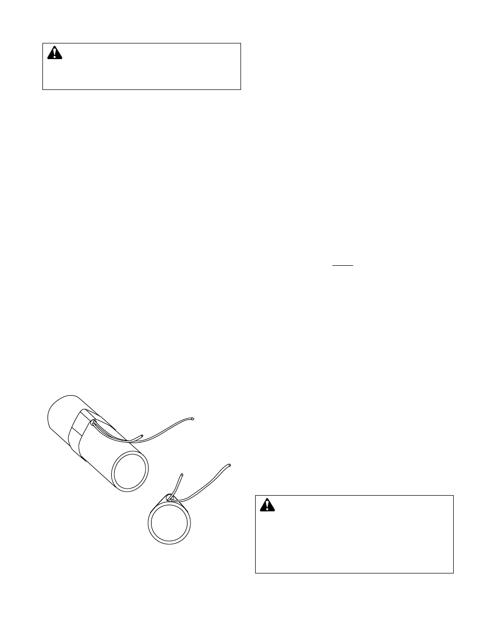
• Strap the boiler return and secondary loop sensors to the
pipe as shown in Figure 4.
• Wrap the pipe and sensor assembly with insulating tape to
insure adequate heat transfer to the sensor.
WIRING THE SENSORS
• The sensor wires have no polarity. Either wire from a sensor
can be connected to the appropriately marked VS screw
terminal (see Figure 5) or the sensor common marked COM.
• Either or both screw terminals marked COM can be used as
the sensor common. They are interchangeable.
• If the sensor wires have been extended, connect the shield to
a COM terminal. Do not connect the shield at the sensor end.
• The two wires from the Secondary loop sensor must be
connected to the VS front screws marked SEC and COM.
• The two wires from the Outdoor sensor must be connected
to the VS front screws marked OUT and COM.
• The two wires from the Boiler return water sensor, if used,
must be connected to the VS front screws marked RTN and
COM. (If not using this sensor, see the NOTE in Low Return
pg. 11.)
WIRING THE VS POWER
• Attach 120VAC line voltage to the two Blue wires extending
from the back of the VS.
• Use wire nuts, or wrap the connections with electrical tape.
• Class 1 voltage must enter the 4" conduit box through a
different opening from any Class 2 wiring.
WIRING THE INJECTION PUMP
• The injection pump MUST be wired to the same power
circuit as the VS control.
• The Red wires provide a solid state switching output to the
Injection pump.
• The Injection pump motor must be a fractional horsepower
permanent split capacitor type motor.
• The Red wires must be directly in series with the pump
power (see Figure 3). The signal can not be wired through
any pilot duty relays or pump starters.
• If used, safety limit switches or HOA switches must be
wired in series with the pump power.
• Use wire nuts, or wrap the connections with electrical tape.
• Class 1 voltages must enter the electrical box through a
different opening from any Class 2 wiring.
WIRING THE SECONDARY LOOP PUMP
• The Black wires provide a Normally Open (N.O.) relay
output for the Secondary loop pump.
• The Black wires are a dry contact output only, They do not
source any power.
• Use wire nuts, or wrap the connections with electrical tape.
• Class 1 voltages must enter the electrical box through a
different opening from any Class 2 wiring.
• Wire the N.O. dry contacts to the pump starter.
WARNING: ELECTRICAL SHOCK HAZARD
Disconnect and lock out power before making elec-
trical connections. Failure to follow these instructions could
result in serious personal injury, death and/or property
damage.
FIG. 4
WARNING: This Bell & Gossett control is strictly an
operating control; it should never be used as a pri-
mary limit or safety control. All equipment must have its
own certified limit and safety controls required by local
codes. The installer must verify proper operation and
correct any safety problems prior to the installation of this
Bell & Gossett control. Failure to follow these instructions
could result in serious personal injury, death and/or
property damage.