Design selection – Bell & Gossett P86272B VS Variable Speed Pump Control User Manual
Page 3
DESIGN SELECTION
To select the correct pump, pipe size and balance valve:
1. Determine the Primary Loop Temperature. This is the
temperature the primary loop will maintain.
2. Determine the Secondary Loop Temperature. This is the
design temperature of the secondary loop. If an outdoor
reset function is being employed, this is the required
temperature of the secondary loop under maximum load.
3. Determine the design temperature drop (
᭝T or delta T) of
the secondary loop. This is the design drop in tem-
perature through the secondary loop. In most radiant
heat applications,
᭝T is 10. Other types of radiation such
as baseboard have a higher design
᭝T.
4. Determine the Maximum Injection Heat Load. This is the
maximum heat requirement of the secondary loop. The
maximum injection heat load is based on the injection
pump running at the highest speed. As the pump speed
is reduced, less heat will be delivered to the secondary
loop.
5. Use the equation below to determine the design injection
flow rate.
Design Injection Flow Rate (GPM) =
Maximum Injection Heat Load (BTU/hr)
500 (T
primary
- T
secondary
+
᭝T
secondary
) (ºF)
6. Use the table below to select the appropriate pump, pipe
size and balance valve.
Design Injection
Injection B&G Circuit
Setter
®
B&G Circuit Setter
®
B&G
Flow Rate (GPM)
Pipe Size
Balance Valve
Valve Setting
Pump
1.5
1
/
2
"
CB-
1
/
2
/ CB-
1
/
2
S
18 / 25
NRF-22
3.5
1
/
2
"
CB-
1
/
2
/ CB-
1
/
2
S
full open / 6
NRF-22
6
3
/
4
"
CB-
3
/
4
/ CB-
3
/
4
S
full open / 12
NRF-22
10
1"
CB-1 / CB-1S
full open / full open
NRF-22
15
1
1
/
4
"
CB-1
1
/
4
/ CB-1
1
/
4
S
5 / 5
NRF-22
24
1
1
/
2
"
CB-1
1
/
2
full open
NRF-33
Example:
1. Primary Loop Temp: 140ºF
2. Secondary Loop Temp: 100ºF
3. Design temperature drop: 10ºF
4. Maximum injection heat load: 150,000 BTU/hr
5. Calculate Injection flow rate
Design Injection Flow Rate (GPM) =
150,000 (BTU/hr)
=
150,000
= 6 GPM
500 (140 - 100 + 10) (ºF) 25,000
6. Injection Pipe size is
3
/
4
", full open CB-
3
/
4
balancing valve and NRF-22
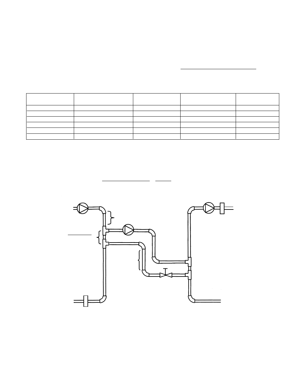
Minimum of 1' of
pipe drop required
to create a thermal
trap
Rule of Thumb
3 pipe diameters
between tees
Minimum of 8 pipe diameters upstream
and 4 pipe diameter downstream of straight
pipe on either side of tees to prevent any
possibility of “jet flow” through the
common piping.
Secondary
Loop
Secondary
Loop Pump
Primary
Loop Pump
Secondary
Loop Sensor
Boiler Return
Sensor
Primary
Loop
Injection Pump
Balance
Valve
3
FIG. 2
Based on (5) feet of pipe, (4) 90° elbows, (4) tees. Correct pipe and pump size calculation for any application should be performed by a qualified engineer or contractor.