Xylem Expert 7060_7070_Modbus User Manual
Page 8
Communication protocol Serie30
Page 14/37
Device Configuration Range (0x02xx):
•
compatible with Class.Group-Version = 5.20-10.XX and later
•
all registers contain 16 bit [15..8][7..0] (1 register), high byte = 0x00 if not specified differently
•
corresponding functionality to Keller Bus functions F32, F33, F66 and F69
MODBUS StAdd
(0xHILO)
Read/
Write
Reg.
Name
DESCRIPTION
0x0200
R/W
UART
UART settings:
Bit 0 .. 3: Baud rate
Baud rate Value = 0: 9’600baud
Baud rate Value = 1: 115’200baud
Bit 4: Parity selection. 0: no Parity, 1: Parity enable
Bit 5: Parity mode. 0: odd parity, 1: even parity
0x0201
R
FILTER_bck
Factory setting for filter value.
0x0202
R
S/N-H
Serial Number High Bytes
0x0203
R
S/N-L
Serial Number Low Bytes
0x0204
R
CFG_P
Active pressure channels (high priority):
Bit 1: P1
Bit 2: P2
0x0205
R
CFG_T
Active Temperature channels (low priority):
Bit 3: T (Temperature sensor)
Bit 4: TOB1 (Temperature of pressure sensor P1)
Bit 5: TOB2 (Temperature of pressure sensor P2)
0x0206
R/W
CFG_CH0
Calculated channel: Byte value (decimal)
0: inactive
1: Difference P1 – P2
2: Difference P2 – P1
3: Square root calculation sqrt(P1)
4: Square root calculation sqrt(P2)
5: Square root calculation sqrt(P1 – P2)
6: Square root calculation sqrt(P2 – P1)
11: Absolute value = |P1|
12: Absolute value = |P1 – P2|
13: Line pressure compensated differential pressure
14: straight line curve fitting of P1
0x0207
R/W
CNT_T
Temperature measurement interval in seconds.
0x0208
R/W
CNT_TCOMP
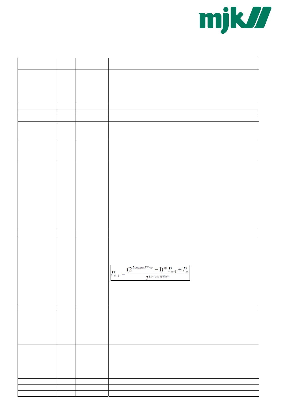
LP_FILT
Value of Bit 3 ... 0 (LowNibble): CNT_TCOMP
After CNT_T * CNT_TCOMP seconds a temperature compensation will be performed.
Value of Bit 7 ... 4 (HighNibble):
Low pass filter for P1 and P2. LowpassFilter = 2
[B7 ... B4]
The formula for the low pass filter is given as:
where:
P
n+1
: new filtered value
P
n
: actual measured value
P
n-1
: old filtered value
0x0209
-
-
Not used (return 0x0000)
0x020A
R/W
FILT_CTRL
Filter setting for one conversion:
Bit 0: Adaptive filter for P1 and P2 (on / off)
Bit 1: Low pass filter for T, TOB1 and TOB2 (on / off)
Bit 2 .. Bit 4: Over sampling ration OSR = 2^(8+Bit 2 ... 4)
Bit 5 .. 6: Amount of samples per averaging: 0 ..3 = 1, 2, 4 or 8 values.
Factory settings see FILTER_ORG.
0x020B
R
DAC_CTRL
Analogue output:
Bit 0: Milli Amperes output (4 .. 20mA)
Bit 1: Voltage output
Bit 4 = 1: P1 is linked to the analogue output
Bit 4 = 0: CH0 is linked to the analogue output
Scaling see function 30/31
0x020C
R
STATUS
Status, the same as the STAT byte from F73.
0x020D
R/W
DEV_ADDR
Device Address
0x020E
R
Class:Group
Firmware-Version