Xylem Expert 7060_7070_Modbus User Manual
Page 3
Communication protocol Serie30
Page 3/37
1
Introduction
This document describes the communications protocol for the Series 30 digital pressure transmitters from KELLER
Druckmesstechnik. In addition to these transmitters, other devices such as data loggers or manometers are also offered. These
products are distinguished by the designation CLASS. Within this device class, the individual device groups are differentiated by
the designation GROUP. All Series 30 pressure transmitters bear the CLASS designation 5.
The software version number consists of following components:
short-designator:
Class
Group
Year
Week
Device group
SW-Version
Series 30 and 40
5
20
SW-Version: release year
SW-Version: release week
In this document, the software version is defined by Class.Group-Year.Week, e.g. 5.20-5.50.
The protocol itself is based on MODBUS, but incorporates optimised functions for the device, these functions are called Keller
bus functions. However, minimum (only fct3) MODBUS RTU functionality is implemented for devices CLASS.GROUP = 5.20
with firmware 2.40 and newer. Full MODBUS support is provided from firmware 5.20-10.XX on.
See Appendix for an overview of differnet versions.
2
Bit transfer layer (physical layer)
2.1
Introduction
The physical connection is provided by the RS485 serial interface. This guarantees good interference immunity and enables a
flexible bus structure, i.e. several devices can be administrated as slaves by a single master. In order to minimise the scope of
cabling, the RS485 is used in half-duplex mode. This means that 2 wires are required for communications and 2 wires for power
infeed.
2.2
Characteristic
In order to operate several devices at one serial interface, they are simply all connected in parallel (RS485A, RS485B, GND and
+Vcc). Before incorporating the devices into the bus, each device must be programmed with a different address.
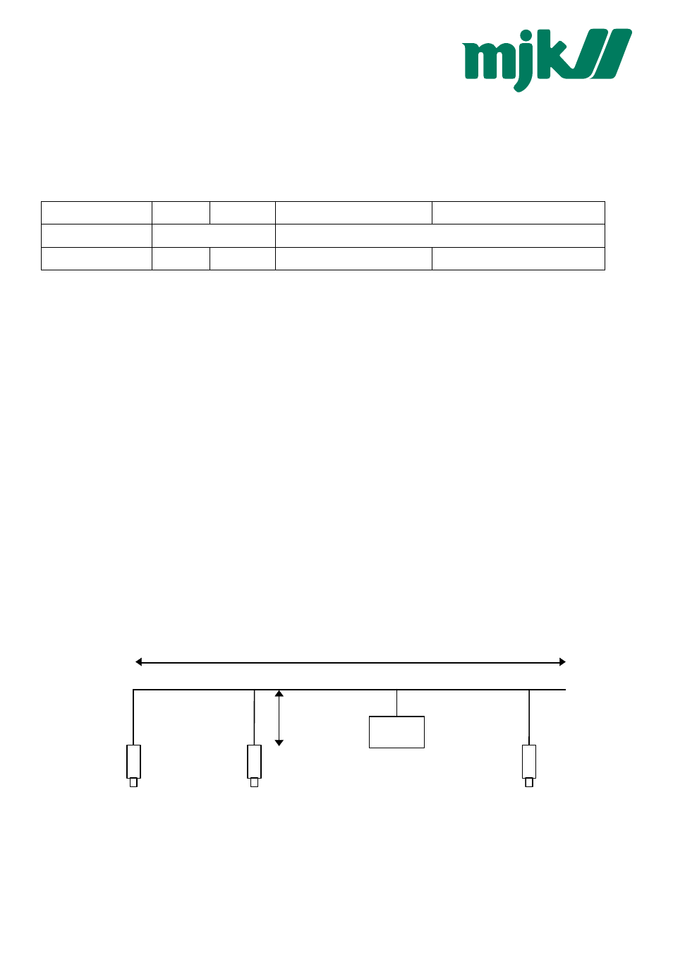
It is possible to configure a network up to a length of 1300 metres with a maximum of 128 devices. Each riser cable may be up to
14 m in length. The employed cable should correspond to specification EIA RS485.
master
max. 1300m
max. 14m
dev. n
dev. 2
dev. 1
MJK