Xylem Expert 7060_7070_Modbus User Manual
Page 26
Communication protocol Serie30
Page 32/37
6.3.2 Analogue Output
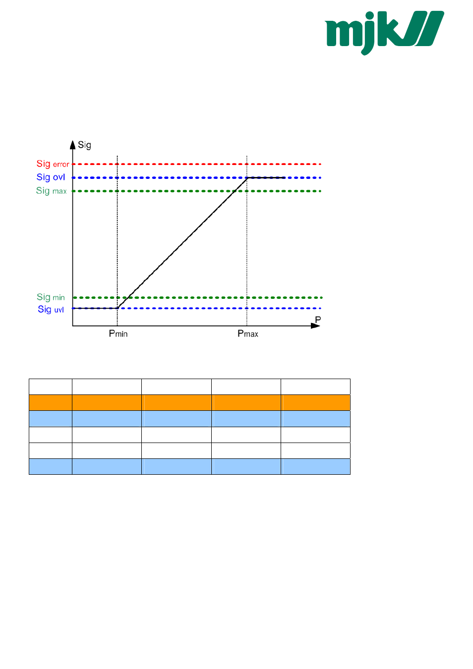
The analogue output has to transfer the error states described in the former chapter and therefore additional analogue states
were introduced. The graph below shows the transfer function between pressure ( in this example the analogue output is a
function of P – however it could also be some other mathematical function using CH0). The black line showes the transfer
function for a positive DAC-gain. The Sig
error
is independent of any scaling function and represents a internal error state (see
table above).
The following table shows possible analogue values for different hardware types:
0-10 V
0-2.5 V
4-20 mA
Dig. represantive
Sig
error
11.6 V
2.9 V
22.5 mA
NaN
Sig
ovl
11 V
2.75 V
21.8 mA
+Inf
Sig
max
10 V
2.5 V
20 mA
value
Sig
min
0 V
0 V
4 mA
value
Sig
uvl
-1 V
-0.3 V
3.3 mA
-Inf
- H-2191 (57 pages)
- H-223 (9 pages)
- H-264 (16 pages)
- H-310 (40 pages)
- H-312 (38 pages)
- H-3301 (24 pages)
- H-3342 (30 pages)
- H-335 (32 pages)
- H-339 (21 pages)
- H-340-CalKit (6 pages)
- H-340 (12 pages)
- H-340SDI (32 pages)
- H-3521 (57 pages)
- H-3531 FlashLite (76 pages)
- H-3551 (42 pages)
- H-3553 (36 pages)
- H-375 04101 WIND MONITOR-JR (18 pages)
- H-4161 (36 pages)
- H-4191 (21 pages)
- H-424MS V1.0 (25 pages)
- H-424MS V1.1 (22 pages)
- H-4271 (22 pages)
- H-4280 (34 pages)
- H-4400 (7 pages)
- H-4401 (6 pages)
- H-5223 (107 pages)
- STORM 3 UPGRADE (4 pages)
- System 5000 BASIC Manual (54 pages)
- System 5000 User Manual (136 pages)
- DH-21 (112 pages)
- BrazedPlate Heat Exchangers (4 pages)
- Heat Exchangers (8 pages)
- GL500 MULTICHANNEL DATA LOGGER (32 pages)
- 4046 ANALOG TO SDI-12 CONVERTER (7 pages)
- 4015 SDI-12 TO ANALOG CONVERTER (5 pages)
- iRIS-CAM Wastewater Security Camera (11 pages)
- SDI-12 Data Logger iRIS 220, iRIS 320, iRIS 350, iRIS 150, iRIS 300 (111 pages)
- iRIS 150 GPRS DATALOGGERS (53 pages)
- iCE3 GPRS Variant (29 pages)
- GL500-2-1 Data Logger (32 pages)
- 3101 CONDUCTIVITY CONTROLLER (11 pages)
- 3675 pH CONTROLLER (9 pages)
- 378 TEMPERATURE CONTROLLER (9 pages)
- Expert 1400 (16 pages)
- Expert 700 (8 pages)