Xylem Expert 7060_7070_Modbus User Manual
Page 32
Communication protocol Serie30
Page 4/37
2.3
RS485 half-duplex details
To ensure best possible operation in an industrial environment Keller uses RS485 driver with tailored characteristics. To provide
compatibility and get full advantage the bus driver of the master device has to support these specifications.
slew rate limited In order to avoid oscillations and interference the signal slew rate is limited. This measure
allows also usage of standard cables or non-standard topologies (e.g. level detectors or
branch lines >> 14m). The more, termination is less critical and has not to be implemented
compulsory at the line ends, a feature important for level detectors.
fail safe
Defined signal level – even in short or open circuit case. This is very important for half-
duplex operation if all devices are in reception mode – here the line is open in case that no
bias resistors are implemented at the master.
1/8 unit load
Input impedance is lower than defined by the RS485 standard, this allows connecting up to
128 devices to the bus.
Termination
Layout: between A and B at the beginning and the end of the transmission line
Value: the same as the line-impedance. Typ.: 120Ohm.
In case of a fail-safe master driver (interface converter to the PC) and a noise-free environment the termination resistor are not
mandatory. To reduce current peaks the resistor value can be chosen higher (1kOhm) or omitted (while transmitting the current
needed for 2x120Ohm is about 50mA).
To ensure a stable communication at least one terminal resistor is necessary (mostly included in the master-RS485 driver)!
One can do without a terminal resistor, if the environment is free of interference and the cable is held short (a few meters).
If the transmitter has additionally an analogue 4...20mA (two wire) output which will be used simultaneously with the serial
communication, it could be useful to communicate without terminal resistor. Otherwise the analogue current signal will have
heavy interferences. See application note: App. Note S30X-011 RS485 and current loop.pdf
The transmitters will never have a terminal resistor built in internally.
Bias-resistors
To keep up having always defined voltages one can switch pull-up respectively pull-down resistors to the transmitter:
From A to +5V and from B to GND. This is necessary when such RS485 drivers are in use which are not fail-save. This is not
necessary for our products when the master is fail-safe.
Common Mode
The common-mode of the data circuit line is +12 / -7V down to GND. It is essential to keep up with this. Always connect the GND
of the RS485 converter of the master with GND of the transmitter!
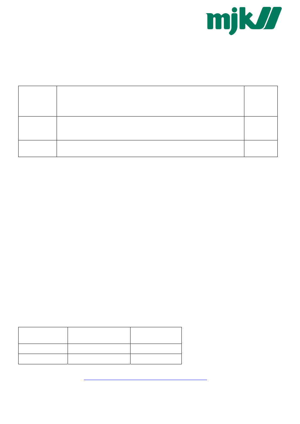
Definition of data circuit line assignments
signal
Designation of Keller and
divers manufacturers…
Designation of the EIA
Standard
inverted (-)
B
A
non-inverted (+)
A
B
Further information on RS485:
http://www.maxim-ic.com/MaximProducts/Interface/rs-485.htm