Xylem Expert 7060_7070_Modbus User Manual
Page 37
Communication protocol Serie30
Page 9/37
4
MODBUS communication
4.1
MODBUS Communication Basics
Mode:
RTU Mode (ASCII is not supported)
Coding System:
8–bit binary, hexadecimal 0–9, A–F
Two hexadecimal characters(bytes) contained in each 8–bit field of the message
Bits per Byte:
1 start bit
8 data bits, least significant bit sent first
1 parity bit: none, even, odd (programmable) – default: none (Keller devices)
1 stop bit
Error Check Field:
2 Byte Cyclical Redundancy Check (CRC)
Baudrate:
programmable 9’600 or 115’200
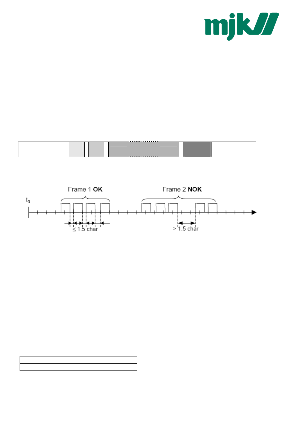
Frame Layout:
> 3.5 char (byte)
start delimiter
8 bit
addr
8 bit
fkt code
n x 8bit
data
(max n = 252)
16 bit
CRC
LOW / HIGH
> 3.5 char (byte)
end delimiter
The entire message frame must be transmitted as a continuous stream of characters. If a silent interval of more than 1.5
character times occurs between two characters, the message frame is declared incomplete and should be discarded by the
receiver.
Bus Addressing:
Unicast addresses: each slave has an address between 1 and 247.
Broadcast addresses: address 0 is used for broadcast frames, the slave accepts the command but must not generate an
answer.
Special addresses: addresses 248 – 255 are reserved. The address 250 is used for non-bus (point-to-point) communication to
address a slave with unspecified or unknown address (not MODBUS standard).
Function Code:
The 8-bit value function code describes the operation that is performed on the slave. Implemented MODBUS functions are
described in the following chapter.
4.2
Using MODBUS with KELLER products
Both protocols are active. For MODBUS only a subset of the MODBUS functionality is implemented and the implemented
MODBUS function codes are not used in the KELLER-protocol. Please note, that the responses are different for both protocols.
Furthermore note that for MODBUS communication NO initialization is required to be performed before any other command.
Attention: The Error Check Field byte alignment differs.
Modbus
KELLER-Protokoll
CRC-16
L:H
H:L
MJK Devices
MJK Products
MJK
-
MJK