Xylem IM158 R04 Model SMVT User Manual
Page 34
32
SMVT Installation, Operation and Maintenance Manual
Maintenance (continued)
30. Install the dowel pin on the pump shaft and loosely assemble the shaft coupling. Do not
tighten the coupling at this point; it should be left loose enough to receive the motor
shaft in the following section.
31. Insert the impeller shim (supplied with the pump) between the shaft coupling and seal
gland. This will lift the shaft/impellers to the running position.
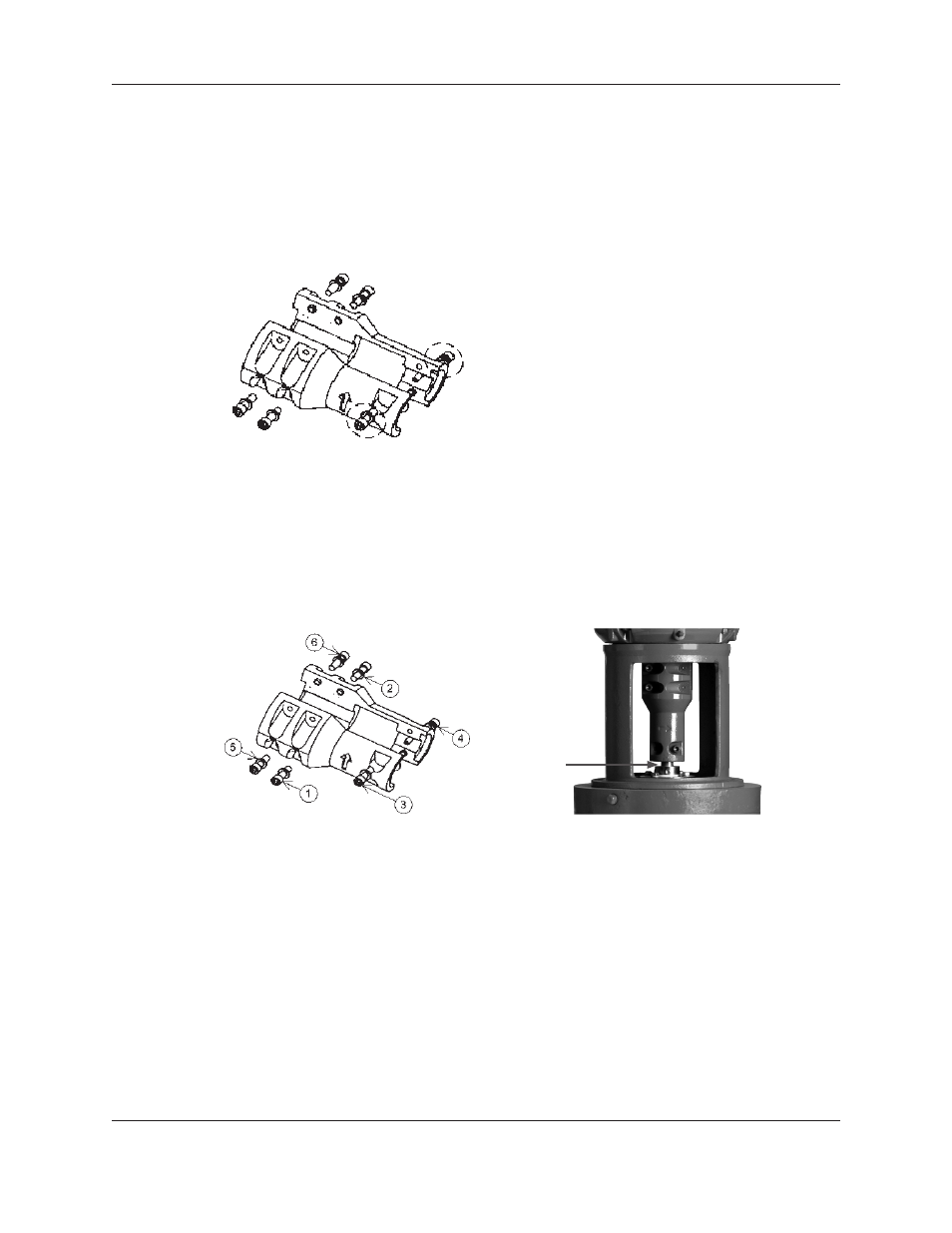
32. Very lightly tighten the (2) socket head cap screws on the pump end of the coupling (refer
to Figure 29). Tighten the coupling evenly; ensure that the coupling is symmetrical on
both the pump and motor shafts. Do NOT torque the cap screws in this step.
Figure 29: Coupling Socket Head Screws
33. Very lightly tighten the remaining (4) socket head screws on the coupling. Tighten the
coupling evenly; ensure that the coupling is symmetrical on both the pump and motor
shafts. Do NOT torque the cap screws in this step.
34. Torque the socket head cap screws on the coupling. Refer to Figure 30 for the proper
torque pattern. See the “Engineering Data” section on page 8 of this manual for the
proper torque value.
Figure 30: Coupling Torque Pattern
Figure 30a: Run Out Measurement Location
35. Remove the impeller shim and retain for future use.
36. Visually inspect the gaps between the coupling to ensure they are symmetrical on both
sides and consistent throughout the length of the coupling.
37. Inspect run out of the shaft between the bottom of the coupling and the mechanical seal
as shown in Figure 30a. If the run out exceeded 0.005”, the coupling must be adjusted. It
is usually most effective to adjust the four bolt section of the coupling.
38. Tighten the set screws on the seal gland. See the “Engineering Data” section on page 8 of
this manual for the proper torque value.
39. Install the (2) coupling guards.