Xylem IM158 R04 Model SMVT User Manual
Page 18
16
SMVT Installation, Operation and Maintenance Manual
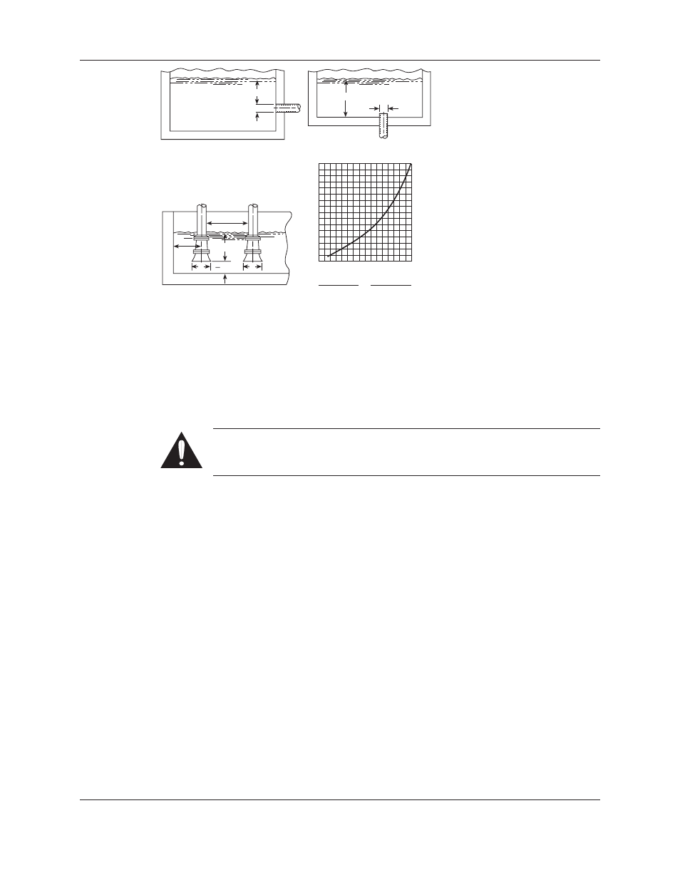
Figures 10-13: Typical Piping Arrangements
Suction Head (Flooded Suction) Conditions
If pump is to be installed below the liquid source, the following MUST be provided:
1. An isolation valve should be installed in the suction line at least two pipe diameters from the
pump suction to permit closing the line for pump maintenance.
WARNING: Do not use the isolation/gate valve to throttle the pump as this
may cause loss of prime, excessive temperatures and damage to pump, voiding
warranty.
2. Keep suction pipe free from air pockets.
3. Piping should be level or slope gradually downward from the source of supply.
4. No portion of the piping should extend below pump suction.
5. The size of the entrance from the supply should be one or two sizes larger than the suction
pipe.
6. The suction pipe must be adequately submerged below the liquid surface to prevent vortices
and air entrainment at the supply. See above illustrations.
Discharge Piping
1. Isolation and check valves should be installed in the discharge line. Locate the check valve
between the isolation valve and the pump. This will permit inspection of the check valve.
The isolation valve is required for priming, regulation of flow and for inspection and
maintenance of the pump. The check valve prevents pump or seal damage due to reverse
flow through the pump when the driver is off.
2. Increasers, if used, should be placed between the pump and check valves.
3. Cushioning devices should be used to protect the pump from surges and water hammer if
quick closing valves are installed in the system.
Installation (continued)
H min.
D
D
H min.
D
D
1.5D
min.
3.0D
min.
H min.
D min.
2
16
15
14
13
12
11
10
9
8
7
6
5
4
3
2
1
H = Min. Submergence in feet
H
1 2 3 4 5 6 7 8 9 10111213141516
V
V = Velocity in feet per second
= GPM x 0.321
Area
GPM x 0.4085
D
2
Figure 10
Figure 12
Figure 11
Figure 13