Xylem IM158 R04 Model SMVT User Manual
Page 15
SMVT Installation, Operation and Maintenance Manual
13
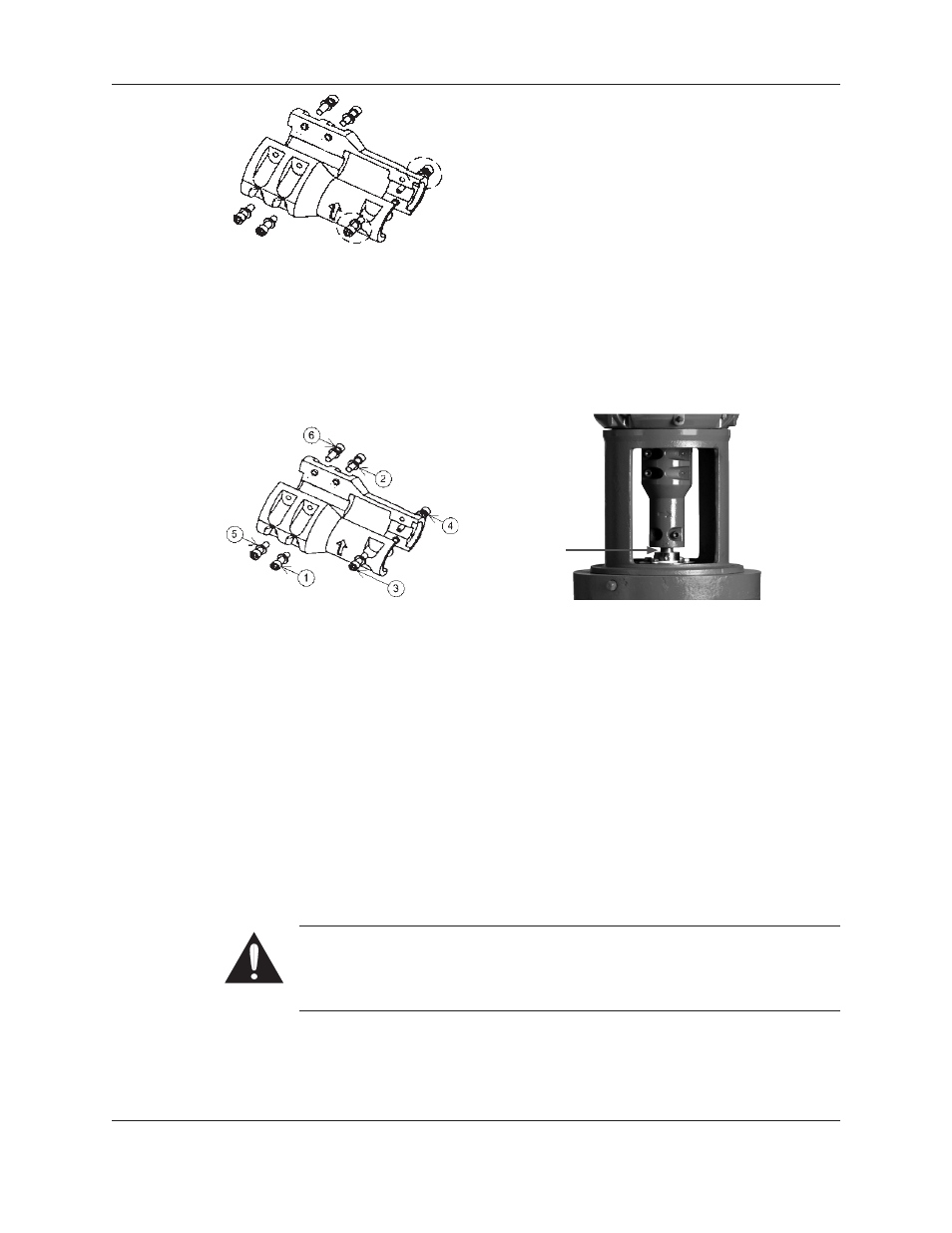
Figure 4: Coupling Socket Head Screws
8. Very lightly tighten the remaining (4) socket head screws on the coupling. Tighten the
coupling evenly; ensure that the coupling is symmetrical on both the pump and motor
shafts. Do NOT torque the cap screws in this step.
9. Torque the socket head cap screws on the coupling. Refer to Figure 5 for the proper
torque pattern. See the “Engineering Data” section on page 8 of this manual for the
proper torque value.
Figure 5: Coupling Torque Pattern
Figure 5a: Run Out Measurement Location
10. Remove the impeller shim and retain for future use.
11. Visually inspect the gaps between the coupling to ensure they are symmetrical on both
sides and consistent throughout the length of the coupling.
12. Inspect run out of the shaft between the bottom of the coupling and the mechanical seal
as shown in Figure 5a. If the run out exceeded 0.005”, the coupling must be adjusted. It
is usually most effective to adjust the four bolt section of the coupling.
13. Tighten the set screws on the seal gland. See the “Engineering Data” section on page 8 of
this manual for the proper torque value.
14. Install the (2) coupling guards.
Piping
General: Guidelines for piping are given in the “Hydraulic Institute Standards” and should
be reviewed prior to installation.
Warning: Never draw piping into place by using force on the suction and
discharge connections of the pump. This may impose dangerous strains on the
unit causing misalignment, poor operation and physical injury and damage to the
equipment.
1. All piping must be supported independently of and line up naturally with the pump suction
and discharge. It MUST NOT place piping loads on the pump.
2. Piping should be no smaller than the pump’s suction and discharge connections and kept as
short as possible, with minimal fittings to minimize friction losses.
Installation (continued)