Xylem IM158 R04 Model SMVT User Manual
Page 27
SMVT Installation, Operation and Maintenance Manual
25
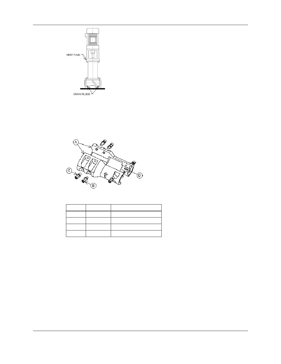
Figure 17: Vent/Drain Plug Locations
3. Remove the (2) coupling guards.
4. Disassemble the coupling by removing the (6) socket head screws. Remove the dowel pin
on the pump shaft. See Figure 18. Retain bolts and dowel pin for reassembly.
Figure 18: Motor Coupling
Item Quantity
Description
A
2
Coupling Half
B
6
Socket Head Cap Screw
C
6
Lock-washer
D
1
Dowel Pin
5. Loosen the set screws on the seal collar.
6. Remove the (4) hex head cap screws on the seal gland. Retain bolts for reassembly.
7. Carefully lift the entire seal assembly from the seal housing by sliding it up the pump
shaft. Discard the entire seal assembly.
8. Lubricate the inside of the mechanical seal assembly (supplied with pump) with grease
(such as Armored AutoGroup “STP” or Dow Corning “111 Grease”) or a mixture of
equal parts non-petroleum hand soap and water. Be sure that there is an o-ring at the
back of the gland flange.
9. Take care to make sure that the pump shaft is clean; it should be free of all burrs, oil, and
grease. The pump shaft should be completely dry before moving on to the next step.
10. To install the new mechanical seal assembly, carefully slide it down the pump shaft until
the gland contacts the mounting surface on the top of the seal housing.
Maintenance (continued)