Xylem IM158 R04 Model SMVT User Manual
Page 30
28
SMVT Installation, Operation and Maintenance Manual
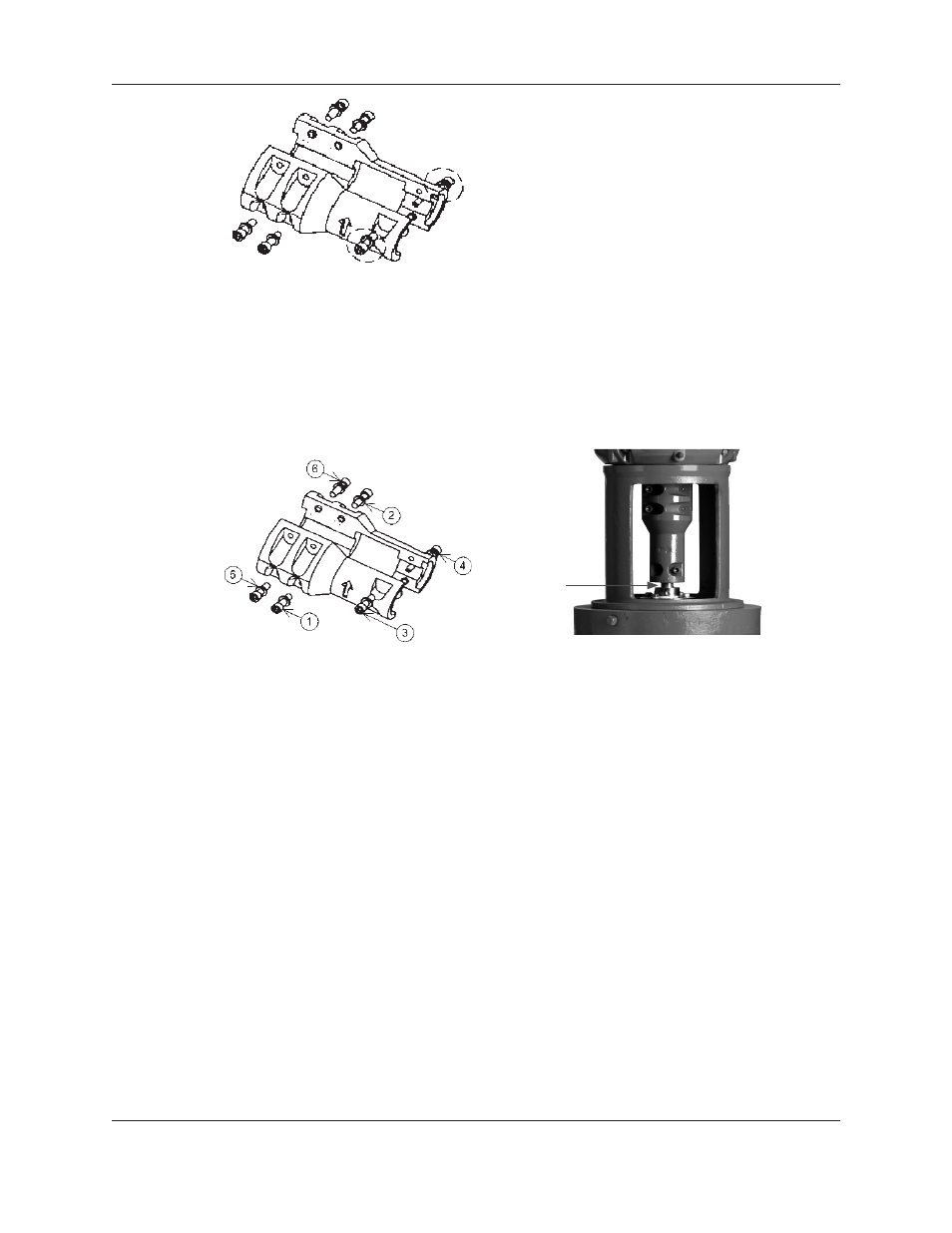
Figure 22: Coupling Socket Head Screws
12. Very lightly tighten the remaining (4) socket head screws on the coupling. Tighten the
coupling evenly; ensure that the coupling is symmetrical on both the pump and motor
shafts. Do NOT torque the cap screws in this step.
13. Torque the socket head cap screws on the coupling. Refer to Figure 23 for the proper
torque pattern. See the “Engineering Data” section on page 8 of this manual for the
proper torque value.
Figure 23: Coupling Torque Pattern
Figure 23a: Run Out Measurement Location
14. Remove the impeller shim and retain for future use.
15. Visually inspect the gaps between the coupling to ensure they are symmetrical on both
sides and consistent throughout the length of the coupling.
16. Inspect run out of the shaft between the bottom of the coupling and the mechanical seal
as shown in Figure 23a. If the run out exceeded 0.005”, the coupling must be adjusted.
It is usually most effective to adjust the four bolt section of the coupling.
17. Tighten the set screws on the seal gland. See the “Engineering Data” section on page 8 of
this manual for the proper torque value.
18. Install the (2) coupling guards.
19. Follow the instructions in “Section IV. Installation” to properly wire the motor.
20. Follow the instructions in “Section V. Commissioning, Startup, Operation, and
Shutdown” for the proper procedures to restart the pump.
Maintenance (continued)