Xylem 19-001-350R2 PACE Integrated Pump Controller Human Machine Interface (HMI) for the Silent Storm VFD Pumping System – Technician Guide User Manual
Page 12
12
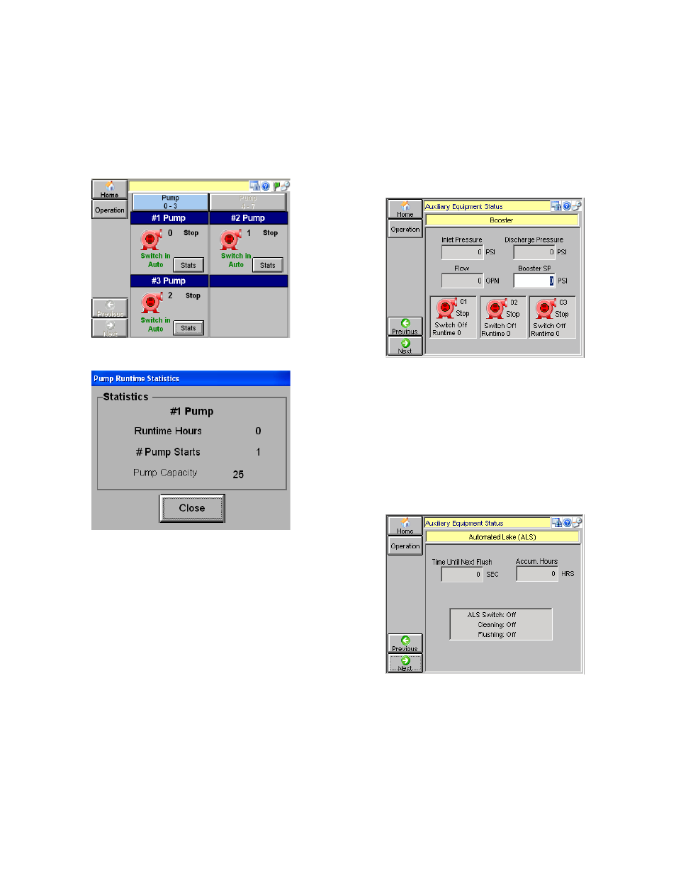
Red, no animation: Stopped pump
Green, rotating center: Running pump
Yellow, flashing center: Fault condition
Individual pump stats (runtime hours, number of
starts, and pump capacity in GPM) can be viewed
by tapping [Stats] for each pump.
Figure 18: Animated Pump Status
Figure 19: Individual Pump Stats
AUXILIARY EQUIPMENT STATUS
Tap [Aux. Equipment Status] from the Operation
menu.
By tapping [Previous] or [Next], you can navigate
the status screens for each device that has been
set up.
NOTE: The screens described below will only be
displayed if they are applicable to the current
system.
Booster Pumps:
Booster Pumps are typically custom features and
the interface depends greatly on the specific site.
However some basic functionality is provided.
Booster pumps typically require an auxiliary PLC.
Up to three booster pumps may be monitored
simultaneously. All fields are read-only with the
exception of ‘Booster SP’. This pressure (PSI) value
remains same for all installed boosters, and is
generally higher than user defined SP.
Red, no animation: Stopped
Green, rotating center: Running
Yellow, flashing center: Fault condition
Tap [Next] to move to the next status screen.
Figure 20: Booster Monitoring Screen
Automated Lake (ALS) Monitoring Screen
This screen is used to monitor the Automated Lake
Screen. ‘Accum Hours’ is the total accumulated
time ALS has been running for. ‘ALS Switch’
denotes the position of ALS switch on the
enclosure. ‘Cleaning’ and ‘Flushing’ denote
if the respective cycles are on or off.
Tap [Next] to move to the next status screen.
Figure 21: ALS Monitoring Screen
Lake Level Controls Monitoring Screen
A maximum of eight lake level controls can be
monitored/configured on this screen. Supervisor
access or higher is required to configure, but guest
level access can view the settings and status
information.