Appendix “a” engineering data, Casing data, Stuff box data – Xylem 8100 Series Centrifugal Pumps AC2515 REV.C User Manual
Page 54: Impeller design data, Shaft and bearing data
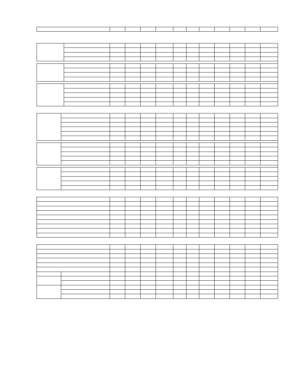
APPENDIX “A” ENGINEERING DATA
Pump Size
6x4x12L 6x4x12XL 6x4x14S
6x4x14L
6x6x9
8x6x9
8x6x10
8x6x12S
8x6x12M
8x6x12L
8x6x12XL
K
CASING
DATA
(All Dimensions in Inches)
125# FF Std
Max. Suction Pressure
75
75
75
75
75
75
75
75
75
75
75
f ASA Flanges
Max. Working Pressure
175
175
175
175
175
175
175
175
175
175
175
h NOMINAL 175 PSI Max. Hydrostatic Test Pressure
262
262
262
262
262
262
262
262
262
262
262
Working Press.
Casing material
Cast I
Cast I
Cast I
Cast I
Cast I
Cast I
Cast I
Cast I
Cast I
Cast I
Cast I
g 250# FF
Max. Suction Pressure
200
200
200
200
200
200
200
200
200
200
200
c NOMINAL 280 PSI Max. Working Pressure
280
280
280
280
280
280
280
280
280
280
280
h Working Press.
Max. Hydrostatic Test Pressure
420
420
420
420
420
420
420
420
420
420
420
Casing material
Ductile I
Ductile I
Ductile I
Ductile I
Ductile I Ductile I Ductile I
Ductile I
Ductile I
Ductile I
Ductile I
g 250# FF
Max. Suction Pressure
300
300
300
300
300
300
300
300
300
300
300
d NOMINAL 400 PSI Max. Working Pressure
400
400
400
400
400
400
400
400
400
400
400
e Working Press.
Max. Hydrostatic Test Pressure
600
600
600
600
600
600
600
600
600
600
600
h
Casing material
Ductile I
Ductile I
Ductile I
Ductile I
Ductile I Ductile I Ductile I
Ductile I
Ductile I
Ductile I
Ductile I
Casing
Wall
Thickness
.375 .375 .50 .50 .50
.50 .50 .50 .44 .44 .44
STUFF BOX DATA
(All Dimensions in Inches)
Packing
Bore
2.625 2.625 2.625 2.625 2.625
2.625 3.25 2.625 3.25 2.625 2.625
Dimensions
Depth
2.56 2.56 2.56 2.56 2.56
2.56 3.50 2.56 3.50 2.56 2.56
Sleeve
O.D.
1.875 1.875 1.875 1.875 1.875
1.875 2.25 1.875 2.25 1.875 1.875
Packing Size/No. Rings W/O S. Cage
6.375
6.375
6.375
6.375
6.375
6.375
6.50
6.375
6.50
6.375
6.375
Packing Size/No. Rings W/ S. Cage
5.375
5.375
5.375
5.375
5.375
5.375
5.50
5.375
5.50
5.375
5.375
Seal
Cage
Width
.50 .50 .50 .50 .50
.50 .75 .50 .75 .50 .50
Mech.
Seal Bore
2.25 2.25 2.25 2.25
2.25
2.25 2.25
On Shaft
Depth
2.62
2.62
2.62
2.62
2.62
2.62
2.62
i Dimensions
Mech. Seal Size (Type 21 or 1)
1.38
1.38
1.38
1.38
1.38
1.38
1.38
Balanced Mech.
Major Dia.-->
1.50
1.50
1.50
1.50
1.50
1.50
1.50
l
{
Seal Size (Type 1B) Minor Dia.-->
1.38
1.38
1.38
1.38
1.38
1.38
1.38
Mech.
Seal Bore
3.00 3.00 3.00 3.00
3.00 3.38 3.00 3.00
On
Sleeves Depth
2.56 2.56 2.62 2.62
2.62 2.88 2.62 2.62
Dimensions
Mech. Seal Size (Type 21 or 1)
1.875
1.875
1.875
1.875
1.875
2.25
1.875
1.875
Balanced
Mech.
Major
Dia.-->
2.00 2.00 2.00 2.00
2.00 2.38 2.00 2.00
l
{
Seal Size (Type 1B) Minor Dia.-->
1.88
1.88
1.88
1.88
1.88
2.25
1.88
1.88
IMPELLER DESIGN DATA
(All Dimensions in Inches)
No. of Vanes
6
7
6
6
6
6
6
5
5
7
7
Inlet Area (Sq. Inches)
19.1
28.4
19.1
22.9
5.9
12.0
15.2
27.0
20.4
38.9
40.6
Inlet
Velocity
per
100
GPM
(Ft/Sec)
1.7
1.1 1.7 1.4 5.4
2.7 2.1 1.2 1.6 .83 .79
Maximum
Diameter
12.8 14.0 13.8 13.8 9.8 9.8 10.0 12.8 12.8 12.8 13.7
Minimum
Diameter
6.0
7.0 6.5 7.0 6.5
6.5 7.6 7.0 6.5 7.0 7.0
Maximum
Sphere
.60
.37 .47 .68 .48
.64 .75 .72 .87 1.0 1.0
WR
^2
for
Maximum
Diameter
(Lbs-Ft^2)
3.1
3.5 7.5 8.0 2.5
2.6 3.1 3.6 3.7 3.8 8.5
j Wear Ring Clearance – Diam. 175# & 280# W.P.
.010-.012 .010-.012 .010-.012 .010-.012 .010-.012 .010-.012 .010-.012 .010-.012 .010-.012 .010-.012 .010-.012
ej Wear Ring Clearance – Diam. 400# W.P.
.020-.024 .020-.024 .020-.024 .020-.024 .020-.024 .020-.024 .020-.024 .020-.024 .020-.024 .020-.024 .020-.024
SHAFT AND BEARING DATA
(All Dimensions in Inches)
Under
Sleeve
1.499 1.499 1.499 1.499 1.499
1.499 1.874 1.499 1.874 1.499 1.499
Under Mech. Seal on Shaft Type 21 or Type 1
1.375
1.375
1.375
1.375
1.375
1.375
1.375
Under Mech. Seal on Shaft Type 1B
1.500
1.500
1.500
1.500
1.500
1.500
1.500
At
Coupling
1.125 1.125 1.125 1.125 1.125
1.125 1.375 1.125 1.375 1.125 1.125
Thru Impeller with Packing – Mech. Seal on Sleeve
1.686
1.686
1.686
1.686
1.687
1.687
1.937
1.686
1.937
1.686
1.686
k Thru Impeller with Mech. Seal on Shaft
1.689
1.689
1.689
1.689
1.689
1.689
1.689
Shaft Span
Bearing to Bearing Centerline
22.90
22.90
22.90
22.90
22.00
25.25
25.25
22.90
25.25
22.90
22.90
Inboard 6206
6206
6206
6206
6206
6206
6208
6206
6208
6206
6206
Ball Bearings
Outboard 5206
5206
5206
5206
5206
5206
5307
5206
5307
5206
5206
Packing
F20-C4 F20-C4 F20-C4 F20-C4 F20-G4
F20-H4
F20-I4 F20-C4 F20-B4 F20-C4 F20-C4
Mech. Seal on Shaft
F20-C5
F20-C5
F20-C5
F20-C5
F20-C5
F20-C5
F20-C5
Frame
Designation
Mech. Seal on Shaft Sleeve
F20-C6
F20-C6
F20-C6
F20-C6
F20-C6
F20-B6
F20-C6
F20-C6
c With 250# FF flanges and 280# PSIG working pressure refer to pump as
M3x2x11S.
d With 250# FF flanges and 400# PSIG working pressure refer to pump as
H3x2x11S.
e For pumps with 400 PSI working pressure, wear ring clearances are doubled.
Derate pump efficiencies by 2 percentage points.
f Flange dimensions are in accordance with ANSI A21.10, AWWA C110 & ANSI
B16.1 class 125.
g Flange dimensions are in accordance with ANSI B16.1 class 250 except flanges
are flat faced, i.e. FF.
h The hydrostatic test will be accordance with the latest edition of the Hydraulic
Institute Standards, test will maintained for a minimum of 5 minutes.
i Type 1 and 21 seals have the same working lengths.
j For bronze impellers and casing rings. For diametral clearances for other
materials, consult factory.
l
Impeller is a light press fit on shaft, do not use construction with stainless steel
impellers.
K
Not available in mechanical seal on shaft arrangement.
54