Xylem 8100 Series Centrifugal Pumps AC2515 REV.C User Manual
Page 50
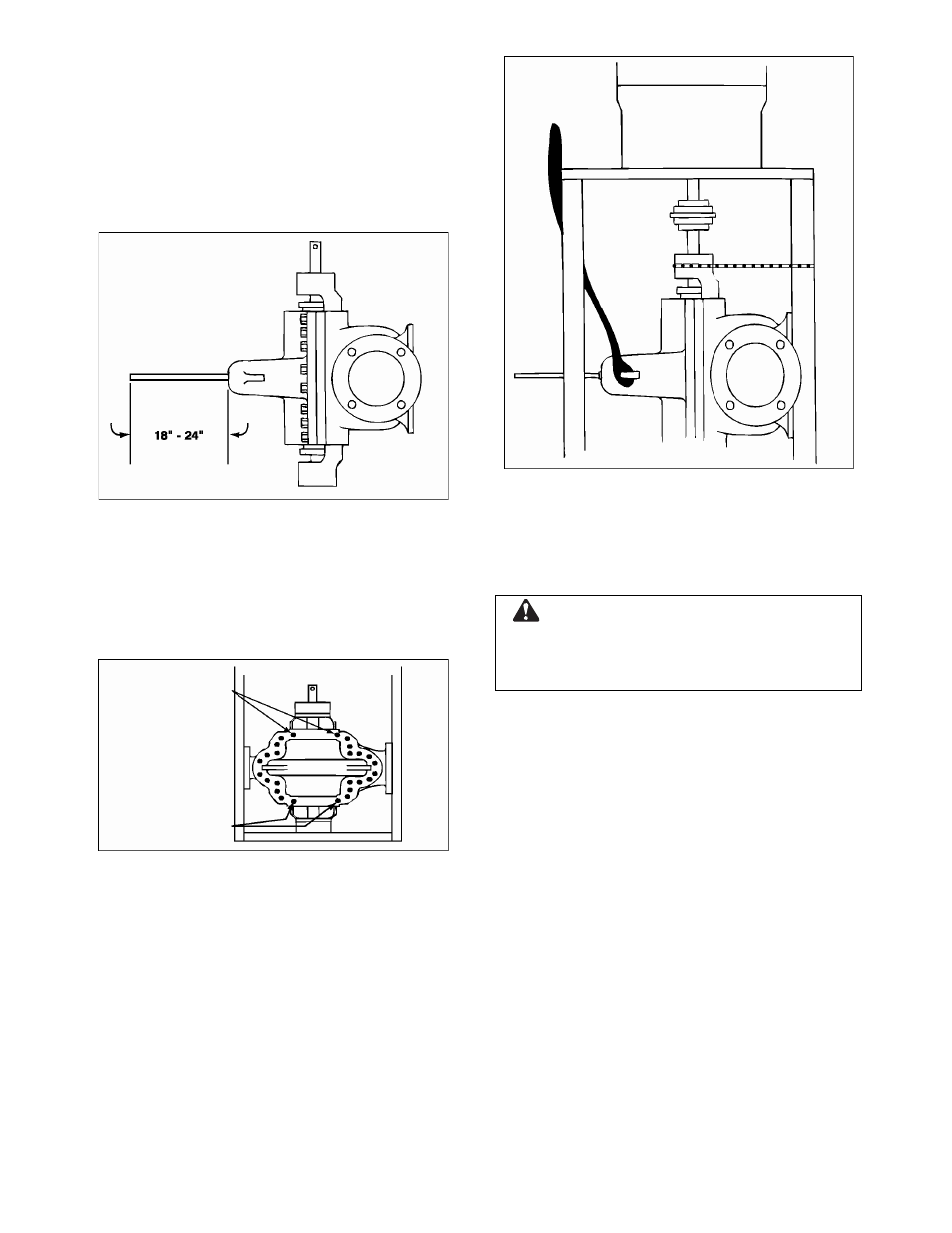
2. Remove the larger of the two pipe plugs
from the top of the casing upper half and
install an 18" to 24" solid bar threaded at
one end into the exposed tapped hole. If a
threaded bar is not available, it is
permissible to use a standard pipe. NOTE:
This bar will be used to stabilize upper half
during disassembly of casing upper half
(See Figure 53).
FIGURE 53 – CASING HALF REMOVAL
3. Disconnect the seal water lines at the stuff
boxes.
4. Remove dowel pins and all parting line
bolts except for two upper most and two
lowest most (See Figure 54).
FIGURE 54 – PARTING LINE BOLTS
5. Sling around casing upper half ears using
nylon sling, pulling slings taught so it is not
possible for slings to slip off (See Figure
55).
6. Remove two lower most bolts and then
one of the two upper most bolts.
CAUTION: Maintain downward pressure
on the stabilizing rod (end furthest from
the pump) during this step.
FIGURE 55 – NYLON SLING AROUND UPPER
CASING HALF
7. While maintaining a downward pressure
on the stabilizer bar, unloosen the
remaining upper most bolt.
WARNING:
Do not remove completely at this point.
Failure to follow these instructions could result in
property damage, severe personal injury, or
death.
UPPERMOST
BOLTS
8. Separate the upper and lower halves by
use of a pry bar between the two halves or
by the use of jacking screws if the top half
is provided with tapped holes.
9. When halves separate, slide upper half
away from lower half, maintain a
downward pressure on the stabilizing rod
and slowly remove completely the
remaining upper most bolt.
LOWERMOST
BOLTS
10. Balancing the upper half with the
stabilizing rod, lower the top half to the
ground allowing the upper half to rotate so
that its main joint flange sets on the
ground (See Figure 56).
50