Xylem 8100 Series Centrifugal Pumps AC2515 REV.C User Manual
Page 40
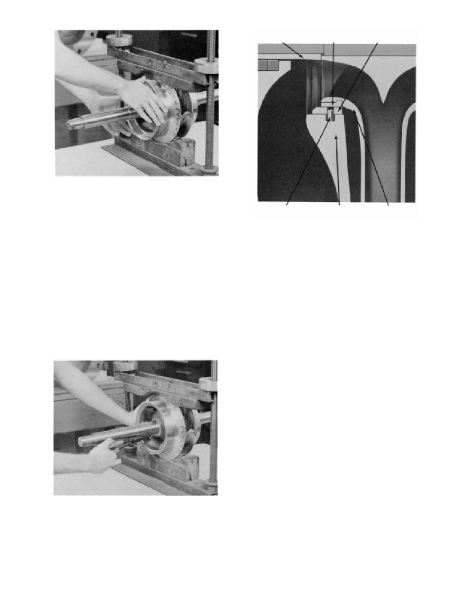
FIGURE 31 – REMOVING CASING RINGS
FROM IMPELLER
10. Remove mechanical seal head (3-402-0)
from the pump shaft.
11. Remove two casing rings (3-003-9) from
the impeller (4-002-0) and remove O-rings
(3-914-2) from each casing ring (See
Figure 31).
12. Remove the impeller retaining ring (3-915-
1) with a retaining ring pliers (Figure 32).
Heat the impeller hub on both ends to
350°F maximum, and pull or push the
impeller from the shaft. (Instead of heating
impeller, you may press impeller off of
shaft, if a press is available.
NOTE: Press away from coupling end.
FIGURE 32 – REMOVING IMPELLER FROM
RETAINING RINGS
NOTE: For impellers with replaceable rings –
remove the rings (0-004-0), if necessary, by
cutting with a cold chisel. (See Figure 33)
(3-009-9)
SLEEVE
(0-004-0)
IMPELLER RING
(3-003-9)
CASING RING
CASING
(2-001-0)
LOCKING PIN
(3-943-9)
IMPELLER
(4-002-0)
FIGURE 33 –IMPELLER WITH WEAR RINGS
13. Remove the impeller key (3-911-1) from
the shaft.
ASSEMBLY (PUMP WITH MECHANICAL
SEALS ON SHAFT)
All bearings, O-rings, lip seals, mechanical seals,
gaskets, impeller rings, and casing rings should be
replaced with new parts during assembly. All
reusable parts should be cleaned of all foreign
matter before reassembling. The main casing joint
gasket can be made using the upper or lower half
as a template. Lay the gasket material on the
casing joint. Trim the gasket by lightly tapping with
a ball peen hammer so that it is flush with the
inside edges of the casing.
NOTE: Precut casing gaskets (2-123-5 and -6)
can be ordered to minimize the amount of
trimming.
1. Assemble the impeller key (3-911-1) in the
shaft key slot.
2. Check the impeller (4-002-0) and casing
to determine the correct relationship (See
Figure 16). Heat the impeller evenly to
300°F maximum to expand the bore.
(Impeller may be pressed onto the shaft
instead of heating if a suitable press is
available, see Figure 34.)
40