Xylem 8100 Series Centrifugal Pumps AC2515 REV.C User Manual
Page 36
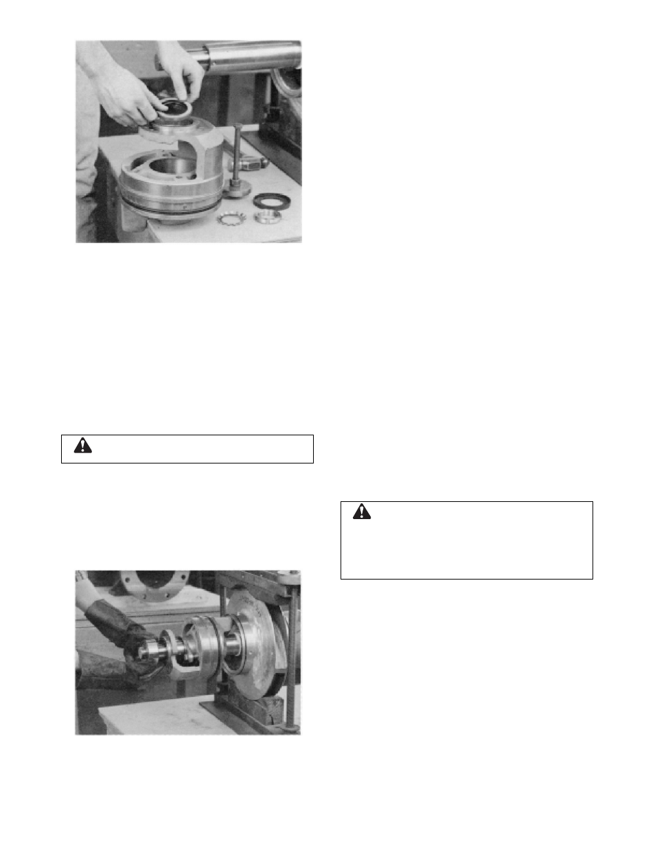
FIGURE 24 – INSTALLING LIP SEAL
10. Lubricate and roll O-ring (3-914-1) into the
groove in each stuffing box.
11. Slide outboard stuff box on the shaft so
that the shaft end extends through the
packing area, but does not enter the lip
seal. This will permit installation of
deflector (3-136-9).
12. Slide the deflector over the shaft end then
carefully push the shaft end through the lip
seal and slide the stuffing box fully onto
the shaft.
CAUTION:
DO NOT EXCEED 275°F.
13. Heat the ball bearing (3-026-4), using
either dry heat or a 10-15% soluble oil and
water solution.
14. Using gloves, slide the heated bearing
onto the shaft against the shaft shoulder
(See Figure 25).
FIGURE 25 – INSTALLING SHAFT BEARING
15. Install lockwasher (3-517-4) and locknut
(3-516-4) on the outboard end of the shaft.
Make certain locknut is secured and then
bend over tabs on lockwasher.
16. Allow the bearing to cool to room
temperature. On grease lubricated
bearings only, coat the exposed sides with
two or three ounces of recommended
grease.
17. On grease lubricated bearings, coat the
inside of the bearing housing (3-025-4)
with grease and slide into place over
bearing. Attaching the bearing housing to
the stuffing box with four cap screws (3-
904-9).
18. Repeat steps 11 through 14, 16 and 17 for
the inboard end.
NOTE: A locknut and lockwasher are not
installed on the inboard end of the shaft.
19. Clean the gasket surfaces of the casing.
Apply Scotch 3M-77 spray adhesive or
equivalent to the lower half of the casing.
20. Within one minute of spraying, set the
untrimmed gaskets (2-123-5 and -6) in
place on the lower half casing, align the
holes in the gaskets with the holes in the
casing and press the gaskets firmly
against the lower half casing face in the
area coated by the adhesive.
21. Trim the gaskets flush with the lower
casing bores, if this has not been done as
yet.
CAUTION:
Machined casing bores must remain sharp
at the casing parting line. Gaskets must be flush
with bore in order to contact O-rings. Leakage can
result around stuff box O-ring if this step is not
properly followed.
22. Set the rotating element in the pump
casing (2-001-0), assuring correct rotation.
Locate both stuffing box tongues in their
respective casing grooves. Locate pins (3-
943-9) in the stuffing box and the casing
wear rings in their respective slots at the
casing parting surface. Correct any O-ring
bulging (See Figure 26).
36