Xylem 8100 Series Centrifugal Pumps AC2515 REV.C User Manual
Page 11
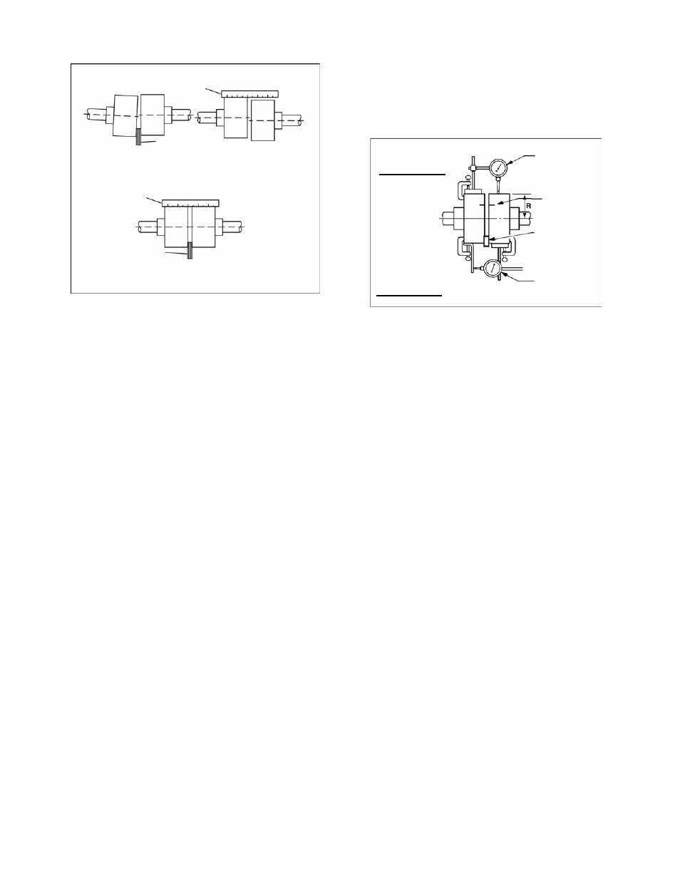
FIGURE 10A – CHECKING ALIGNMENT
(METHOD 1)
Method 2 – For Orange Hytrel Insert, 3500
RPM Operation, or All Other Coupler
Types Except as Noted Below
(See Figure 10B)
a. Make sure each hub is secured to its
respective shaft and that all connecting
and/or spacing elements are removed at
this time.
b. The gap between the coupling hubs is set
by the manufacturer before the units are
shipped. However, this dimension should
be checked. (Refer to the coupling
manufacturer’s specifications supplied
with the unit.)
c. Scribe index lines on coupling halves as
shown in Figure 10B.
d. Mount dial indicator on one hub as shown
for parallel alignment. Set dial to zero.
e. Turn both coupling halves so that index
lines remain matched. Observe dial
reading to see whether driver needs
adjustment (See paragraph i below).
f. Mount dial indicator on one hub as shown
for angular alignment. Set dial to zero.
g. Turn both coupling halves so that index
lines remain matched. Observe dial
reading to see whether driver needs
adjustment (See paragraph i below).
h. Assemble coupling. Tighten all bolts and
set screw(s). It may be necessary to
repeat steps c through f for a final check.
i. For single element couplings, a
satisfactory parallel misalignment is
.004"T.I.R., while a satisfactory angular
misalignment is .004"T.I.R. per inch of
radius R (See Figure 10B).
STRAIGHT EDGE
FEELER GAGE
PARALLEL
ALIGNMENT
DIAL
INDICATOR
INCORRECT ALIGNMENT
ANGULAR ALIGNMENT
PARALLEL ALIGNMENT
STRAIGHT EDGE
INDEX LINE
RESILIENT
SEPARATOR
FEELER GAGE
CORRECT ALIGNMENT
ANGULAR
ALIGNMENT
DIAL
INDICATOR
FIGURE 10B – CHECKING ALIGNMENT
(METHOD 2)
Grid Couplings
NOTE: The following procedure is intended
for mounting and alignment of Rexnord
Industries, LLC. and Clarke Fire Protection
Products, Inc., Tapered Grid Couplings.
Adequate lubrication is essential for
satisfactory operation. Grease supplied by
the coupling manufacturer is highly
recommended. Other greases to be used
should be approved by the coupling
manufacturer.
Alignment is shown using a spacer bar and
straight edge. Rexnord Industries, LLC. and
Clarke Fire Protection Products, Inc. state
this practice has been proven for many
industrial applications. Superior alignment
can be achieved through the use of dial
indicators as shown above.
1. Clean all metal parts using non-flammable
solvent.
2. Lightly coat seals with coupling vendor
supplied grease and place on shafts
before mounting shaft hubs.
3. Install keys and mount hubs with flange
faces flush with shaft ends or as otherwise
specified.
4. Reposition hubs on shafts as required to
achieve the required hub gap shown in
Figure 10H or otherwise specified. The
length of engagement on each shaft
11