Ap3105na/nv/nl/nr, Operation description – Diodes AP3105NA/NV/NL/NR User Manual
Page 9
AP3105NA/NV/NL/NR
Document number: DS36542 Rev. 1 - 2
9 of 13
www.diodes.com
September 2013
© Diodes Incorporated
AP3105NA/NV/NL/NR
A Product Line of
Diodes Incorporated
Operation Description
(Cont.)
System Protection and Pin Fault Protection
The AP3105NA/NV/NL/NR provides versatile system and pin fault
protections. The OCP comparator realizes the cycle-by-cycle
current limiting (OCP). In universal input line voltage, the IC realizes
the constant over load protection (OLP). VCC over voltage
protection can be applied as the primary OVP or opto-coupler
broken protection. The AP3105NA/NV/NL/NR also has pin fault
connection protection including floating and short connection. The
floating pin protection include the SENSE, FB, etc.. The short pin
protection includes the CTRL pin short protection. When these pins
are floated or CTRL pin is shorted to ground, PWM switching will be
disabled, thus protecting the power system.
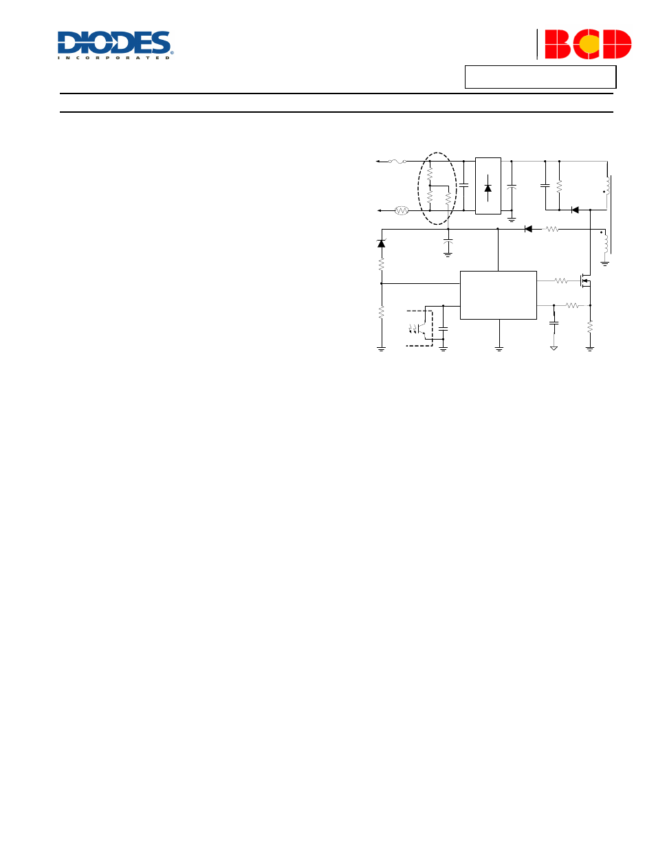
Latch Protection Function
For some applications, the system requires the latch protection
function. The CTRL pin has two kinds of modes to trigger the latch
protection: high level trigger and low level trigger. The low threshold
is 0.5V and high threshold voltage is 2.5V. Some version will have
only one mode. Once the latch protection is triggered, the IC will
disable the output signal, and the bulk capacitor provides the
energy to IC through the startup resistor to ensure the IC disable
the output (latch mode). This mode will be not released until the AC
input is shut off. So, the de-latch time is mainly depending on the
HV startup bulk capacitor value. Therefore, if the system wants a
short de-latch time, it is better for the startup resistor take power
from the point before the rectifier bridge as illustrated in Figure 2.
VCC
GND
FB
CTRL
AP3105NA/NV/NL/NR
SENSE
AC Mains
(90V to 265V)
C
BUS
GATE
1
2
3
4
5
6
Figure 2