Diodes ZXMS6001N3 User Manual
Page 5
ZXMS6001N3
© Zetex Semiconductors plc 2008
f
Integrated protection functions are designed to prevent IC destruction under fault conditions described in the
datasheet. Fault conditions are considered as "outside" normal operating range. Protection functions are not designed
for continuous, repetitive operation.
Parameter
Symbol
Min
Typ
Max
Unit
Conditions
Protection Functions (f)
Minimum input voltage
for over temperature
protection
V
PROT
4
3.5
V
Ttrip>150°C
Maximum input voltage
for over temperature
protection
V
PROT
7
6
V
Ttrip>150°C
Thermal Overload Trip
Temperature
T
JT
150
175
°C
Thermal hysteresis
8
°C
Unclamped single pulse
inductive energy
Tj=25
°C
E
AS
550
mJ
I
D(ISO)
=0.7A, V
DD
=32V
Unclamped single pulse
inductive energy
Tj=150
°C
E
AS
200
mJ
I
D(ISO)
=0.7A, V
DD
=32V
Inverse Diode
Source drain voltage
V
SD
1
V
V
IN
=0V, -I
D
=1.4A
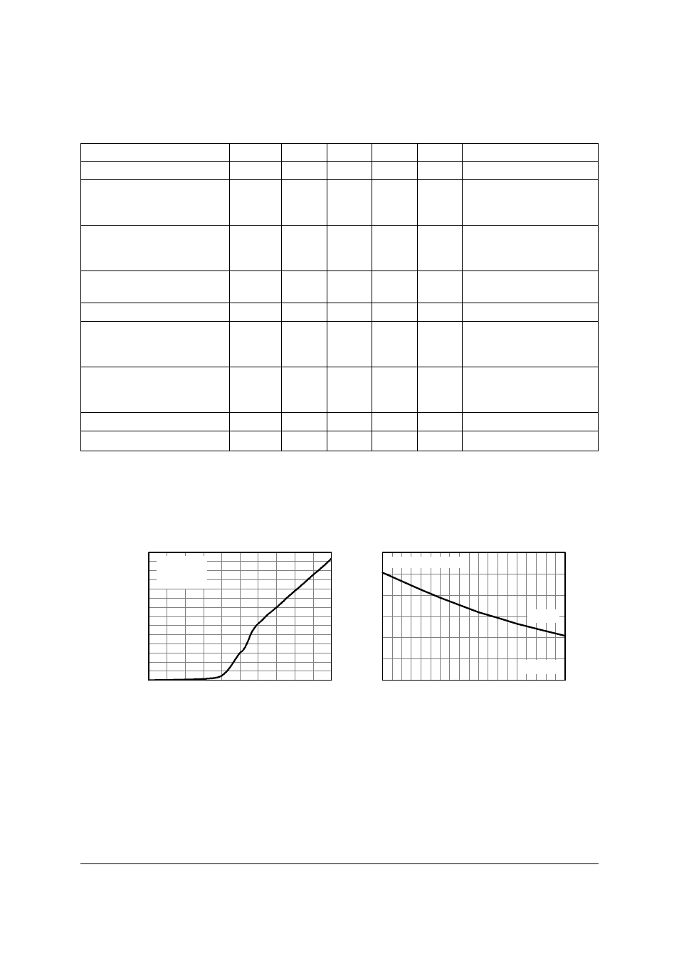
0
1
2
3
4
5
0
50
100
150
200
250
300
350
V
DS
= 13.5V
V
IN
= 5V
I
IN
-
I
npu
t
C
urr
en
t (
µ
A
)
V
IN
- Input Voltage (V)
-40 -20
0
20
40
60
80 100 120 140
0
1
2
3
V
IN
= 5V
Single Pulse = 300µs
V
DS
= 12V
Current Limit v Temperature
Input Current v Input Voltage
Temperature (°C)
Id
Li
m
C
u
rr
e
n
t Li
m
it
(A
)