AVSL 169.011-169.013 MU-series MIDI/USB Keyboard Controllers User Manual
Page 3
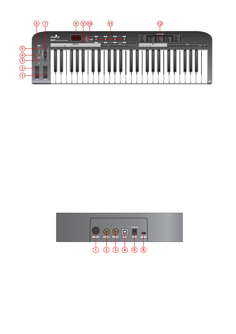
Top Panel
1. MODULATION Wheel - Expression wheel, assignable to one of 148 MIDI control parameters. Initial setting is MIDI
control number 1: Modulation.
2. PITCH BEND Wheel
– Spring loaded expression wheel, assignable to one of 148 MIDI control parameters. Initial
setting is MIDI control number 146: Pitch Bend
3. DATA +/- Buttons
– Increment/decrement data entry buttons, assignable to one of 160 MIDI control parameters. Initial
setting is MIDI control number 154: Octave Shift
4. OCTAVE/TRANSPOSE Indicator - When either of these indicators is on, it indicates that there is an upper/lower
octave shift. When the indicator flashes slowly, it indicates that there is an upper/lower transpose shift. When the
indicator flashes quickly, it indicates that there is a simultaneous upper/lower octave and transpose adjustment. When
the indicator is off, there is no octave or transpose shift.
5. EDIT Button
– Switches edit function of note keys on/off
6. EDIT Indicator
– Indicates that the EDIT function is active (keys will operate as labelled above each note)
7. SLIDER
– Fader style controller, assignable to one of 148 MIDI control parameters. Initial setting is MIDI control number
147: Master Volume
8. 3-digit LED Display
– Shows program/parameter values for MIDI and EDIT functions
9. SWITCH Button
– Toggles the rotary dials between 2 groups of control settings: R1-R4 / R5-R8
10. Dial Function Group LEDs
– Indicate which group of parameters is active for rotary dials.
11. R1- R8 Dials
– 4 data entry dials, individually assignable to one of 160 MIDI control parameters, divided across 2
groups. Initial channel of R1-R4 is 0. Initial controller numbers are 152, 153, 156, 157, which control Program, Channel,
Tempo and Keyboard Velocity Curve respectively. The initial channels of R5-R8 are 0-3. Initial controller number is 7,
which controls the volume of channels 0-3 respectively. The parameter group of R1-R4 and R5-R8 is switched by the
SWITCH button.
12. Constant Controller Parameter chart
– A table showing standard MIDI parameter values
Rear Panel
1. MIDI OUT
– 5-pin DIN MIDI output to control external sound module or keyboard
2. PEDAL A
– Pedal A input 6.3mm jack for switching or continuous type pedal control, assignable to one of 152
controllers. Initial setting is Soft Pedal.
3. PEDAL B
– Pedal B input 6.3mm jack for switching or continuous type pedal control, assignable to one of 152
controllers. Initial setting is Sustain Pedal.
4. USB
– USB type B connector for connecting to PC or Mac computer
5. DC9V
– Input jack for optional 9Vdc power adapter (300mA, polarity positive-to-centre)
6. OFF/ON
– Power switch