Chapter 1, Chapter 1: product introduction – Asus M5A97 LE R2.0 User Manual
Page 34
1-20
Chapter 1: Product introduction
Chapter 1
Chapter 1
Chapter 1
Chapter 1
DO NOT forget to connect the fan cables to the fan connectors. Insufficient air flow inside
the system may damage the motherboard components. These are not jumpers! DO NOT
place jumper caps on the fan connectors.
•
The CPU_FAN connector supports a CPU fan of maximum 1A (12 W) fan power.
•
Only the CPU_FAN and CHA_FAN1/2/3 connectors support the ASUS Fan Xpert
feature.
•
If you install two VGA cards, we recommend that you plug the rear chassis fan cable
to the motherboard connector labeled CHA_FAN1/2 for better thermal environment.
M5A97 LE R2.0
M5A97 LE R2.0 Fan connectors
CPU_FAN
CHA_FAN1
CPU F
AN PWM
CPU F
AN IN
CPU F
AN PWR
GND
CHA_FAN2
CHA
F
AN PWM
CHA
F
AN IN
CHA
F
AN PWR
GND
CHA_FAN3
CHA
F
AN PWM
CHA
F
AN IN
CHA
F
AN PWR
GND
GND
CHA FAN PWR
CHA FAN IN
CHA FAN PWM
3.
CPU and chassis fan connectors (4-pin CPU_FAN, and 4-pin CHA_FAN1/2/3)
Connect the fan cables to the fan connectors on the motherboard, ensuring that the
black wire of each cable matches the ground pin of the connector.
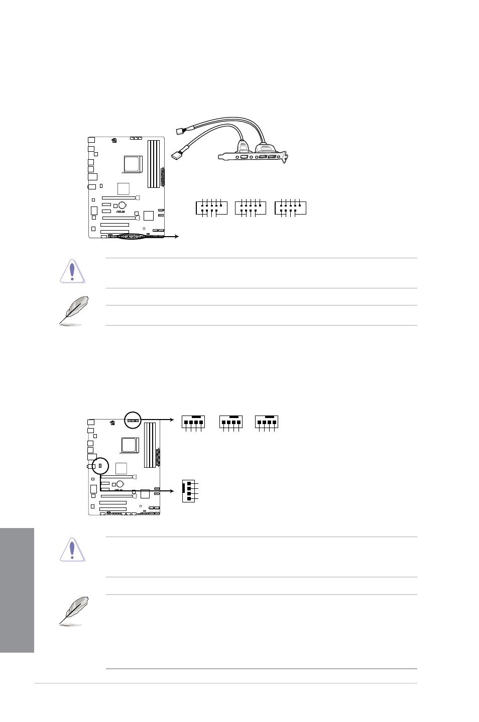
2.
USB 2.0 connectors (10-1 pin USB910, USB1112, USB1314)
These connectors are for USB 2.0 ports. Connect the USB module cable to any of
these connectors, then install the module to a slot opening at the back of the system
chassis. These USB connectors comply with USB 2.0 specification that supports up to
480Mbps connection speed.
Never connect a 1394 cable to the USB connectors. Doing so will damage the
motherboard!
The USB 2.0 module is purchased separately.
M5A97 LE R2.0
M5A97 LE R2.0 USB2.0 connectors
USB+5V USB_P12- USB_P12+ GND NC
USB+5V
USB_P11- USB_P11+
GND
USB1112
PIN 1
USB+5V USB_P14- USB_P14+ GND NC
USB+5V
USB_P13- USB_P13+
GND
USB1314
PIN 1
USB+5V USB_P10- USB_P10+ GND NC
USB+5V USB_P9- USB_P9+
GND
USB910
PIN 1