Chapter 1 – Asus M5A97 LE R2.0 User Manual
Page 37
M5A97 LE R2.0
1-23
Chapter 1
Chapter 1
Chapter 1
Chapter 1
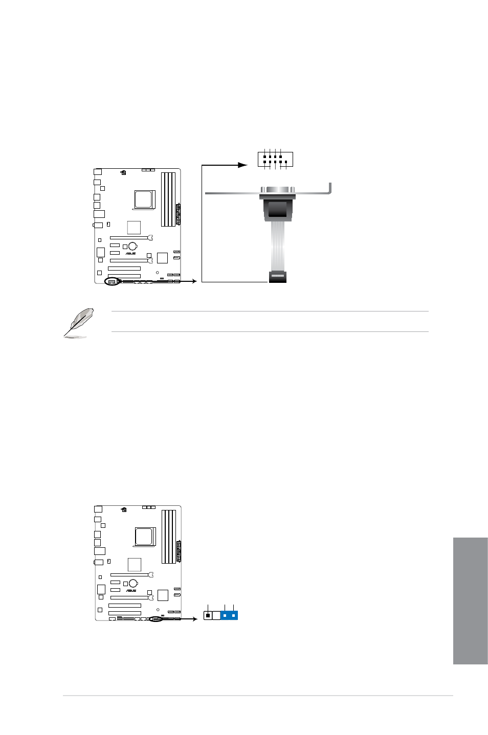
7.
Serial port connector (10-1 pin COM1)
This connector is for a serial (COM) port. Connect the serial port module cable to this
connector, then install the module to a slot opening at the back of the system chassis.
The COM module is purchased separately.
M5A97 LE R2.0
M5A97 LE R2.0 Serial port (COM1) connector
PIN 1
COM1
DCD TXD GND RTS
RI
RXD DTR DSR CTS
8.
Chassis intrusion connector (4-1 pin CHASSIS)
This connector is for a chassis-mounted intrusion detection sensor or switch. Connect
one end of the chassis intrusion sensor or switch cable to this connector. The chassis
intrusion sensor or switch sends a high-level signal to this connector when a chassis
component is removed or replaced. The signal is then generated as a chassis intrusion
event.
By default, the pin labeled “Chassis Signal” and “Ground” are shorted with a jumper
cap. Remove the jumper caps only when you intend to use the chassis intrusion
detection feature.
M5A97 LE R2.0
M5A97 LE R2.0 Chassis intrusion connector
+5VSB_MB
Chassis Signal GND
CHASSIS