Chapter 1 – Asus M5A97 LE R2.0 User Manual
Page 35
M5A97 LE R2.0
1-21
Chapter 1
Chapter 1
Chapter 1
Chapter 1
•
We recommend that you connect a high-definition front panel audio module to this
connector to avail of the motherboard high-definition audio capability.
•
If you want to connect a high definition front panel audio module to this connector, set
the Front Panel Type item in the BIOS to [HD]. See section 3.5.7 Onboard Devices
Configuration for details.
•
The front panel audio I/O module is purchased separately.
5.
Front panel audio connector (10-1 pin AAFP)
This connector is for a chassis-mounted front panel audio I/O module that supports
either High Definition Audio or AC`97 audio standard. Connect one end of the front
panel audio I/O module cable to this connector.
M5A97 LE R2.0
M5A97 LE R2.0 Front panel audio connector
AAFP
AGND NC SENSE1_RETUR
SENSE2_RETUR
PORT1 L PORT1 R PORT2 R
SENSE_SEND
PORT2 L
HD-audio-compliant
pin definition
PIN 1
AGND NC NC
NC
MIC2
MICPWR
Line out_R
NC
Line out_L
Legacy AC’97
compliant definition
Ensure that the audio device of Sound playback is Realtek High Definition Audio (the
name may be different based on the OS). Go to Start > Control Panel > Sounds and
Audio Devices > Sound Playback to configure the setting.
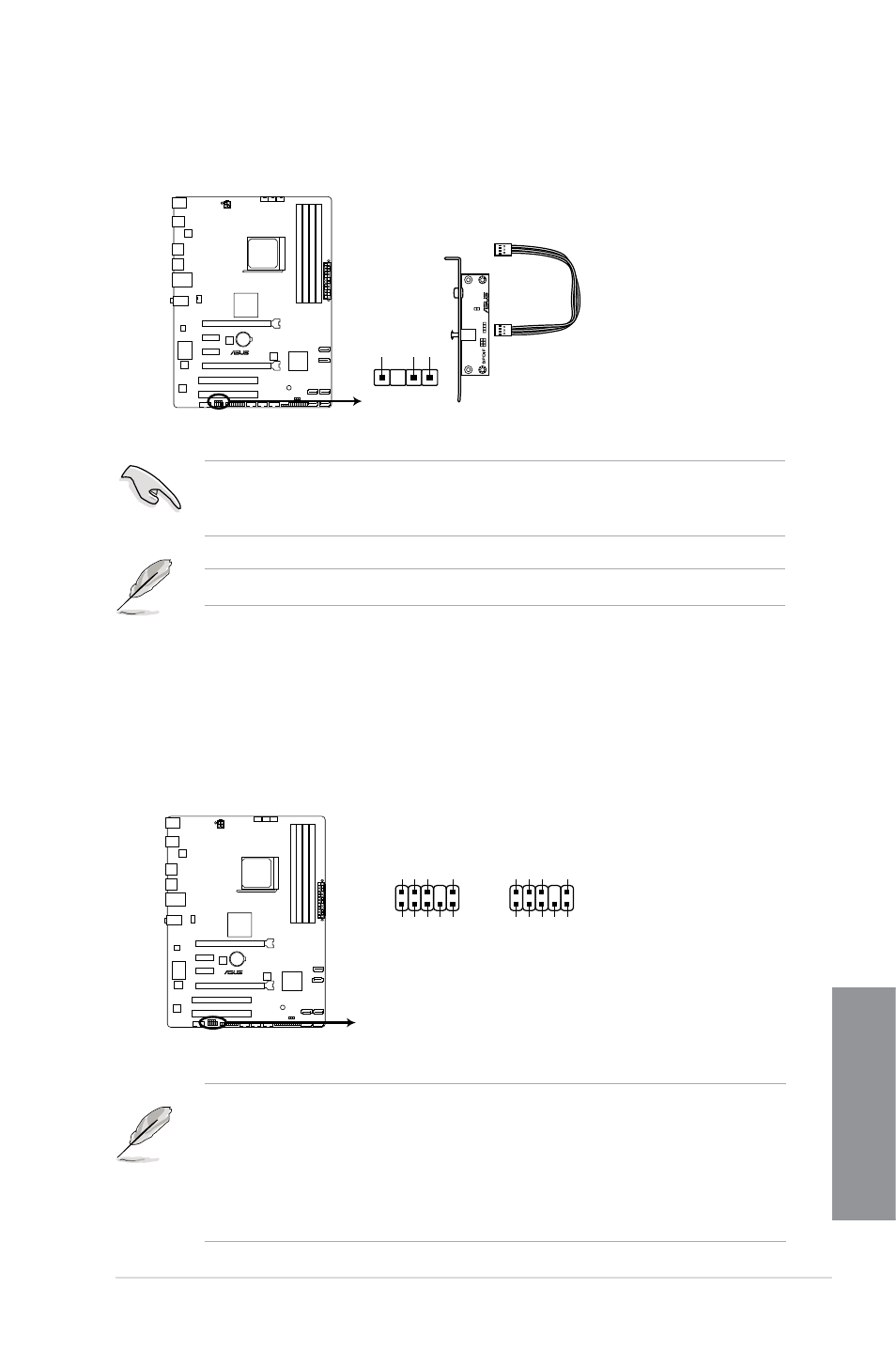
The S/PDIF module is purchased separately.
SPDIF_OUT
+5V
SPDIFOUT GND
M5A97 LE R2.0
M5A97 LE R2.0 Digital audio connector
4.
Digital audio connector (4-1 pin SPDIF_OUT)
This connector is for an additional Sony/Philips Digital Interface (S/PDIF) port.