Asus P5LD2-V User Manual
Page 30
2 - 6
2 - 6
2 - 6
2 - 6
2 - 6
C h a p t e r 2 : H a r d w a r e i n f o r m a t i o n
C h a p t e r 2 : H a r d w a r e i n f o r m a t i o n
C h a p t e r 2 : H a r d w a r e i n f o r m a t i o n
C h a p t e r 2 : H a r d w a r e i n f o r m a t i o n
C h a p t e r 2 : H a r d w a r e i n f o r m a t i o n
I n t e r n a l c o n n e c t o r s
I n t e r n a l c o n n e c t o r s
I n t e r n a l c o n n e c t o r s
I n t e r n a l c o n n e c t o r s
I n t e r n a l c o n n e c t o r s
P a g e
P a g e
P a g e
P a g e
P a g e
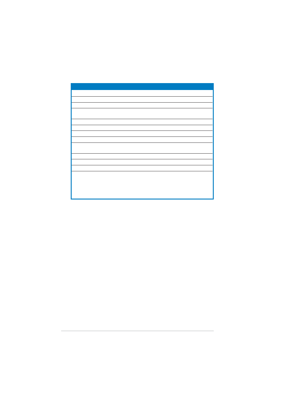
1.
Floppy disk drive connector (34-1 pin FLOPPY)
2-25
2.
ITE IDE connectors (40-1 pin PRI_EIDE [red], SEC_EIDE [red])
2-25
3.
Primary IDE connector (40-1 pin PRI_IDE)
2-26
4.
Serial ATA connectors (7-pin SATA1 [red], SATA2 [red],
2-26
SATA3 [black], SATA4 [black])
5.
Optical drive audio connector (4-pin CD)
2-28
6.
Front panel audio connector (10-1 pin AAFP)
2-28
7.
USB connectors (10-1 pin USB56, USB78)
2-29
8.
GAME/MIDI port connector (16-1 pin GAME)
2-29
9.
CPU, Chassis, and Power Fan connectors (4-pin CPU_FAN,
2-30
3-pin CHA_FAN2, PWR_FAN)
10.
Chassis intrusion connector (4-1 pin CHASSIS)
2-29
11.
ATX power connectors (24-pin EATXPWR, 4-pin ATX12V)
2-31
12.
System panel connector (20-1 pin PANEL)
2-32
System power LED (Green 3-pin PLED)
Hard disk drive activity LED (Red 2-pin IDE_LED)
System warning speaker (Orange 4-pin SPEAKER)
ATX power button/soft-off button (Yellow 2-pin PWRSW)
Reset button (Blue 2-pin RESET)