Asus P5N32-SLI SE Deluxe User Manual
Page 61
A S U S P 5 N 3 2 - S L I S E D e l u x e
A S U S P 5 N 3 2 - S L I S E D e l u x e
A S U S P 5 N 3 2 - S L I S E D e l u x e
A S U S P 5 N 3 2 - S L I S E D e l u x e
A S U S P 5 N 3 2 - S L I S E D e l u x e
2 - 3 5
2 - 3 5
2 - 3 5
2 - 3 5
2 - 3 5
8 .
8 .
8 .
8 .
8 .
IEEE 1394
IEEE 1394
IEEE 1394
IEEE 1394
IEEE 1394 p o r t
p o r t
p o r t
p o r t
p o r t connector
c o n n e c t o r
c o n n e c t o r
c o n n e c t o r
c o n n e c t o rsssss
(10-1 pin IE1394_1
(10-1 pin IE1394_1
(10-1 pin IE1394_1
(10-1 pin IE1394_1
(10-1 pin IE1394_1,
,
,
,
, I E 1 3 9 4 _
I E 1 3 9 4 _
I E 1 3 9 4 _
I E 1 3 9 4 _
I E 1 3 9 4 _2
2
2
2
2 )))))
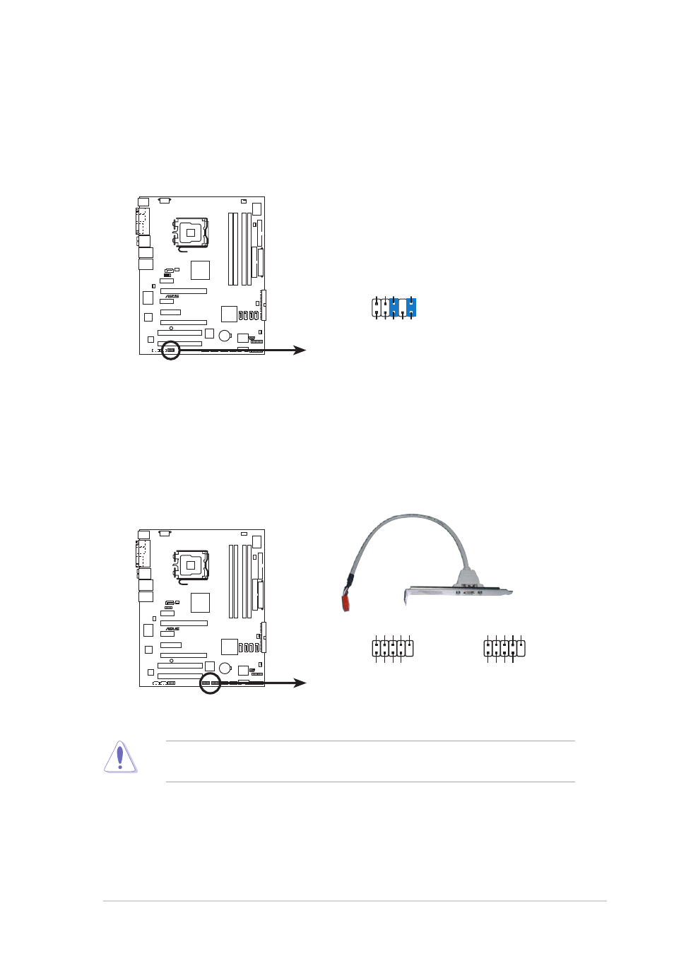
These connectors are for IEEE 1394 ports. Connect the IEEE 1394
module cable to this connector, then install the module to a slot
opening at the back of the system chassis.
Never connect a U S B c a b l e
U S B c a b l e
U S B c a b l e
U S B c a b l e
U S B c a b l e to the IEEE 1394a connectors.
Doing so will damage the motherboard!
7 .
7 .
7 .
7 .
7 .
F r o n t p a n e l a u d i o c o n n e c t o r ( 1 0 - 1 p i n F P _ A U D I O )
F r o n t p a n e l a u d i o c o n n e c t o r ( 1 0 - 1 p i n F P _ A U D I O )
F r o n t p a n e l a u d i o c o n n e c t o r ( 1 0 - 1 p i n F P _ A U D I O )
F r o n t p a n e l a u d i o c o n n e c t o r ( 1 0 - 1 p i n F P _ A U D I O )
F r o n t p a n e l a u d i o c o n n e c t o r ( 1 0 - 1 p i n F P _ A U D I O )
This connector is for a chassis-mounted front panel audio I/O module
that supports legacy AC ‘97 audio standard. Connect one end of the
front panel audio I/O module cable to this connector.
P5N32-SLI SE Deluxe
®
P5N32-SLI SE Deluxe Front panel audio connector
FP_AUDIO
BLINE_OUT_L
MIC2
Line out_R
Line out_L
BLINE_OUT_R
NC
MICPWR
+5V
A
AGND
P5N32-SLI SE Deluxe
®
P5N32-SLI SE Deluxe IEEE 1394 connector
IE1394_2
1
TP
A2-
GND
TPB2-
+12V
GND
TP
A2+
GND
TPB2+
+12V
IE1394_1
1
TP
A2-
GND
TPB2-
+12V
GND
TP
A2+
GND
TPB2+
+12V