Asus P5N32-SLI SE Deluxe User Manual
Page 57
A S U S P 5 N 3 2 - S L I S E D e l u x e
A S U S P 5 N 3 2 - S L I S E D e l u x e
A S U S P 5 N 3 2 - S L I S E D e l u x e
A S U S P 5 N 3 2 - S L I S E D e l u x e
A S U S P 5 N 3 2 - S L I S E D e l u x e
2 - 3 1
2 - 3 1
2 - 3 1
2 - 3 1
2 - 3 1
2 .
2 .
2 .
2 .
2 .
I D E c o n n e c t o r ( s ) ( 4 0 - 1 p i n P R I _ I D E , S E C _ I D E )
I D E c o n n e c t o r ( s ) ( 4 0 - 1 p i n P R I _ I D E , S E C _ I D E )
I D E c o n n e c t o r ( s ) ( 4 0 - 1 p i n P R I _ I D E , S E C _ I D E )
I D E c o n n e c t o r ( s ) ( 4 0 - 1 p i n P R I _ I D E , S E C _ I D E )
I D E c o n n e c t o r ( s ) ( 4 0 - 1 p i n P R I _ I D E , S E C _ I D E )
The onboard IDE connectors are for Ultra DMA (133/)100/66 signal
cables. There are three connectors on each Ultra DMA 133/100/66
signal cable: blue, black, and gray. Connect the blue connector to
the motherboard's IDE connector, then select one of the following
modes to configure your devices.
•
Pin 20 on the IDE connector is removed to match the covered hole
on the Ultra DMA cable connector. This prevents incorrect insertion
when you connect the IDE cable.
•
Use the 80-conductor IDE cable for Ultra DMA 100/66 IDE devices.
Black or gray
D r i v e j u m p e r
D r i v e j u m p e r
D r i v e j u m p e r
D r i v e j u m p e r
D r i v e j u m p e r
M o d e
M o d e
M o d e
M o d e
M o d e
C a b l e
C a b l e
C a b l e
C a b l e
C a b l e
s e t t i n g
s e t t i n g
s e t t i n g
s e t t i n g
s e t t i n g
o f d e v i c e ( s )
o f d e v i c e ( s )
o f d e v i c e ( s )
o f d e v i c e ( s )
o f d e v i c e ( s )
c o n n e c t o r
c o n n e c t o r
c o n n e c t o r
c o n n e c t o r
c o n n e c t o r
Single device
Cable-Select or Master
-
Black
Two devices
Cable-Select
Master
Black
Slave
Gray
Master
Master
Slave
Slave
If any device jumper is set as "Cable-Select," make sure all other device
jumpers have the same setting.
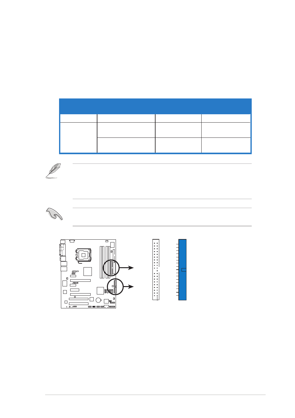
P5N32-SLI SE Deluxe
®
P5N32-SLI SE Deluxe IDE connectors
NOTE: Orient the red markings
(usually zigzag) on the IDE
ribbon cable to PIN 1.
PRI_IDE
PIN 1
SEC_IDE