Hardware setup, Asus mew-b user’s manual 39 – Asus MEW-B User Manual
Page 39
ASUS MEW-B User’s Manual
39
3. HARDWARE SETUP
Connectors
3. H/W SETUP
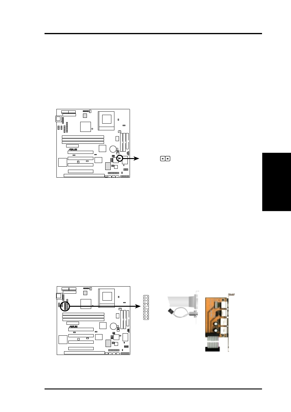
18) Chassis Intrusion Lead (2 pin CHASSIS)
This lead is for a chassis designed for chassis intrusion detection. After-market
toggle switches may also be installed to the chassis panel or on any removable
components. Two wires should be available from the chassis to connect to this
lead. When any chassis component is removed, the contact should open and the
motherboard will record a chassis intrusion event. The event can then be pro-
cessed by software such as LDCM. If the chassis intrusion lead is not used, a
jumper cap must be placed over the pins to prevent unnecessary power loss.
MEW-B Chassis Open Alarm Lead
CHASSIS
0
1
®
MEW-B
19) USB, PS/2 Mouse, Infrared Module Connector (USBMIR, 18-1 pin block)
If you want to use PS/2 mouse, USB, or infrared (IrDA) devices, you need to
purchase an optional USB/MIR connector set. You may use the bundled PS/2
mouse/parallel port connector set if you just want to use a PS/2 mouse. Either
connector set connects to the 18-pin block and mounts to an open slot on your
computer’s chassis. The system will direct IRQ12 to the PS/2 mouse if one is
detected. If not detected, expansion cards can use IRQ12. See PS/2 Mouse
Control in 4.4 Advanced Menu and USB Function in 4.4.3 PCI Configura-
tion. See Serial IR and Consumer IR Connectors for details on the infrared
connector.
0
1
®
MEW-B
MEW-B PS/2 Mouse, USB, IrDA Module Connector
PS/2
Mouse
Infrared
USB 0
USB 1
Optional USB
1
9
18
10
USB
Parallel Connector
PS/2 Mouse Connector
9: +5 Volt
8: (no connection)
7: Ground
6: PS/2 Mouse Clock
5: USB +5 Volt
4: Ground
3: USB Port 0 +
2: USB Port 0 -
1: USB +5 Volt
18: Infrared Transmit
17: Infrared Receive
16: Ground
15: PS/2 Mouse Data
14: Key
13: Ground
12: USB Port 1 +
11: USB Port 1 -
10: USB +5 Volt