Hardware setup – Asus MEW-B User Manual
Page 34
34
ASUS MEW-B User’s Manual
Connectors
3. H/W SETUP
3. HARDWARE SETUP
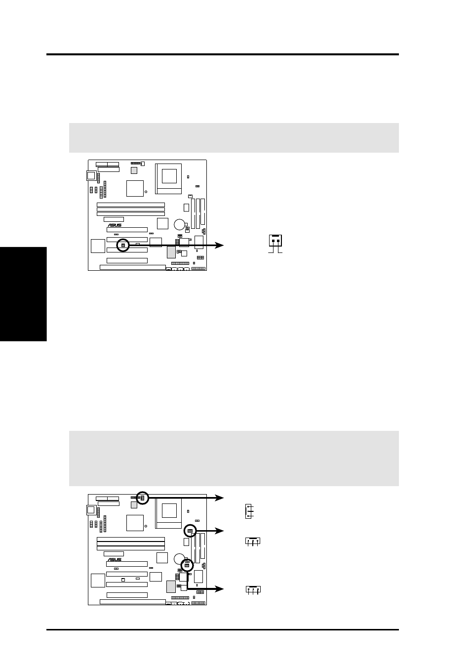
7)
Wake-On-Ring Connector (2-pin WOR)
This connector connects to internal modem cards with a Wake-On-Ring output.
The connector powers up the system when a ringup packet or signal is received
through the internal modem card. NOTE: For external modems, Wake-On-
Ring is detected through the COM port.
IMPORTANT:
This feature requires that PWR Up On Modem Act is set to
Enabled (see 4.5.1 Power Up Control).
0
1
®
MEW-B
MEW-B Wake-On-Ring Connector
WOR
RI#
Ground
2
1
8)
Chassis, CPU, & Power Supply Fan Connectors (3-pin CHA_, CPU_, PWR_FAN)
These connectors support cooling fans of 350mA (4.2 Watts) or less. Orientate
the fans so that the heat sink fins allow airflow to go across the onboard heat
sink(s) instead of the expansion slots. Depending on the fan manufacturer, the
wiring and plug may be different. The red wire should be positive, while the
black should be ground. Connect the fan’s plug to the board taking into consid-
eration the polarity of the connector.
NOTE: The “Rotation” signal is to be used only by a specially designed fan with
rotation signal. The Rotations per Minute (RPM) can be monitored using ASUS
PC Probe Utility or Intel LDCM Utility (see 6. SOFTWARE REFERENCE).
WARNING!
The CPU and/or motherboard will overheat if there is no airflow
across the CPU and onboard heatsinks. Damage may occur to the motherboard
and/or the CPU fan if these pins are incorrectly used. These are not jumpers,
do not place jumper caps over these pins.
0
1
®
MEW-B
MEW-B 12-Volt Cooling Fan Power
Chassis Fan Power
GND
Rotation
+12V
Power Supply Fan
CPU Fan Power
GND
Rotation
+12V
GND
Rotation
+12V