Hardware setup, Asus mew-b user’s manual 37 – Asus MEW-B User Manual
Page 37
ASUS MEW-B User’s Manual
37
3. HARDWARE SETUP
Connectors
3. H/W SETUP
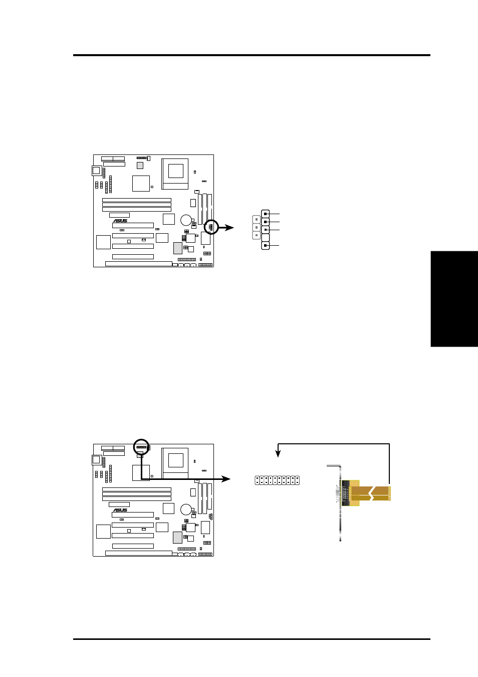
13) SMBus Connector (5-1 pin SMB)
This connector allows you to connect SMBus (System Management Bus) de-
vices. SMBus devices communicate by means of the SMBus with an SMBus
host and/or other SMBus devices. SMBus is a specific implementation of an
I
2
C bus, which is a multi-device bus; that is, multiple chips can be connected to
the same bus and each one can act as a master by initiating data transfer.
SMBCLK
Ground
SMBDATA
+5V
1
MEW-B SMBus Connector
SMB
0
1
®
MEW-B
14) Digital LCD Header (20-pin DFP)
This optional header requires a digital LCD cable connector. Connect the digi-
tal LCD cable to this header and mount the bracket to the chassis on a free
expansion slot. NOTE: If both CRT and digital LCD monitors are used, the
CRT will take precedence. This connector is for a digital LCD panel; an analog
LCD panel comes with a 15-pin VGA cable connector to be used on the moni-
tor connector. The connector with bracket shown here is provided with the LCD
model.
0
1
®
MEW-B
MEW-B LCD Header
DFP
1
11
10
20
11: FDDCDAT
12: 0+5V
13: TXC-
14: GND
15: TX0+
16: TX1-
17: GND
18: TX2+
19: (No connection)
20: (No connection)
1: FDDCCLK
2: PLSENSE
3: GND
4: TXC+
5: TX0-
6: GND
7: TX1+
8: TX2-
9: GND
10: (No connection)