Iii. installation – Asus P/I-P65UP8/CP6ND User Manual
Page 29
ASUS P/I-P65UP8 User’s Manual
29
III. INSTALLATION
(Connectors)
III. INST
ALLA
TION
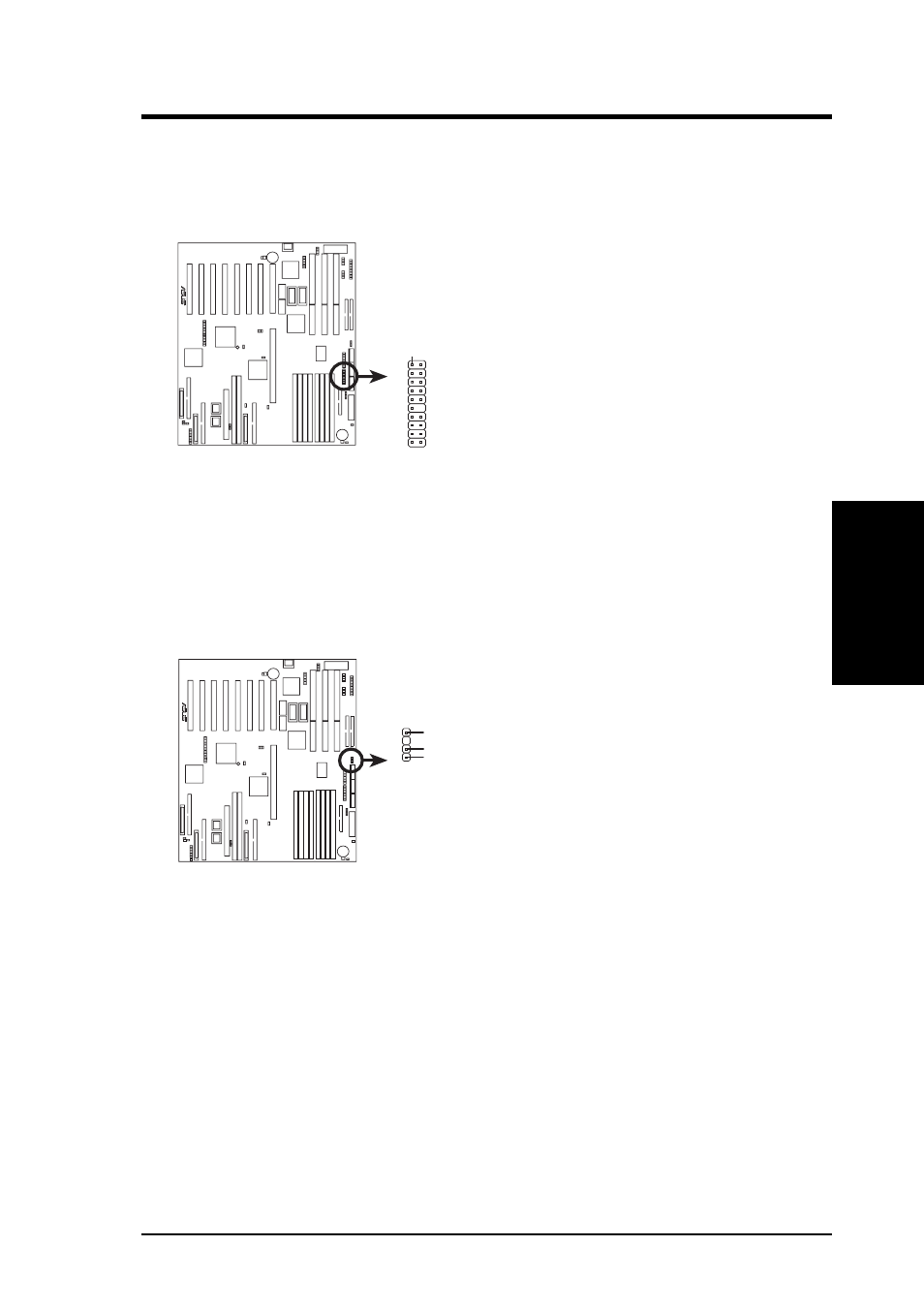
11. ASUS System Monitoring Module Connector (20-1 pin SERVER_CON)
This connector is for an optional ASUS System Monitoring Module for moni-
toring system temperature and fan RPM.
Server Connector
R
Pin 1
12. Chassis Open Alarm Connector (4-1 pin CHASSIS)
This connector is for an optional ASUS System Monitoring Module for moni-
toring chassis open/close status. A high level signal to the chassis signal lead
will indicate to the system that the chassis has been opened.
R
Chassis Connector
For the chassis open alarm feature to work, you must connect
the optional ASUS Server Managment Module to these pins.
The +5V power comes from the power supply, when the A/C
is connected. With the A/C power disconnected, the +3V power
comes from the onboard button cell battery.
Ground
Power (+3V/+5V)
Chassis Signal
- P5B Premium Vista Edition (188 pages)
- P5B (140 pages)
- P5B (56 pages)
- P5KPL-VM/1394/SI (94 pages)
- M2N68-CM (28 pages)
- P5GD1-VM (92 pages)
- P5AD2-E Premium (2 pages)
- P5GD1-VM (88 pages)
- P5AD2 Premium (8 pages)
- DELUXE A7N8X-E (114 pages)
- P5KPL-AM SE (62 pages)
- P5KPL-AM SE (40 pages)
- P5KPL-AM SE (38 pages)
- P4S8X-X (64 pages)
- P5K-VM (98 pages)
- K8V-X SE (82 pages)
- M2N68-AM SE2 (40 pages)
- P4P800 SE (16 pages)
- P4P800 SE (125 pages)
- DELUXE SERIES M3A32-MVP (176 pages)
- P5AD2 Deluxe (148 pages)
- M4A79 Deluxe (122 pages)
- A7V266-E (108 pages)
- Application Manual (4 pages)
- Application Manual (8 pages)
- Application Manual (2 pages)
- Application Manual (6 pages)
- Application Manual (9 pages)
- Application Manual (3 pages)
- Application Manual (1 page)
- Application Manual (5 pages)
- Application Manual (11 pages)
- Application Manual (10 pages)
- M4A88T-I DELUXE (44 pages)
- M4A88T-I DELUXE (70 pages)
- P9X79 DELUXE (2 pages)
- RAMPAGE IV GENE (1 page)
- P9X79 (156 pages)
- P8H61-M PLUS V3 (64 pages)
- A85XM-A (78 pages)
- M4A78L-M LE (64 pages)
- M2N68-AM (96 pages)
- M2N68-AM (62 pages)
- M2N68-AM (38 pages)
- Blitz Formula (2 pages)