Iii. installation, Asus p2b-d/p2b-ds motherboard layout, 10 asus p2b-d/p2b-ds user’s manual – Asus P2B-DS User Manual
Page 10: Motherboard layout iii. inst alla tion, Intel 440bx agpset, Intel piix4e chipset
10
ASUS P2B-D/P2B-DS User’s Manual
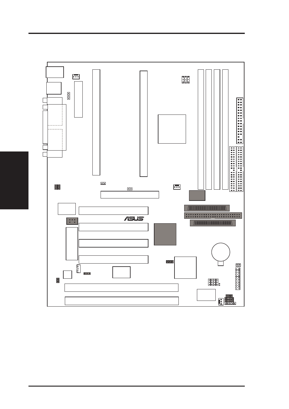
III. INSTALLATION
ASUS P2B-D/P2B-DS Motherboard Layout
PWR_FAN
FS0
FS1
FS2
USB
PS/2
35
34
68
35
34
68
R
Wake-On-LAN
Hardware
Monitor
BF3
BF2
BF1
BF0
S82093AA
Chipset
CPU_FAN
IDELED
COM 2
COM 1
JP18
CHA_FAN
CLRTC
IrDA
Adaptec
AIC-7890AB
Chipset
Intel
PIIX4E
Chipset
ASUS
A97127F
Chipset
68-Pin Ultra2 SCSI Connector
68-Pin Wide SCSI Connector
1
1
Keyboard Power
2Mbit Flash EEPROM
(Programmable BIOS)
1
1
NOTE: Grayed items are optional/reserved for future use.
JP4
JP5
SMB
Intel
440BX
AGPset
A
TX Power Connector
Slot1 for CPU 1
Slot1 for CPU 2
DIMM Socket 3 (64 bit, 168 pin module)
DIMM Socket 2 (64 bit, 168 pin module)
DIMM Socket 1 (64 bit, 168 pin module)
DIMM Socket 0 (64 bit, 168 pin module)
Multi-I/O
Chip
PCI Slot 1
PCI Slot 2
PCI Slot 3
MOUSE (TOP PORT)
KEYBOARD (BOTTOM)
USB 1(TOP PORT)
USB 2 (BOTTOM)
Accelerated Graphics Port
50-Pin SCSI Connector
P
A
RALLEL
PORT
Floppy Disk Drives
Primary IDE
Secondary IDE
CMOS Power
(CR2032 3V
Lithium Cell)
ISA Slot 1
ISA Slot 2
BUS FREQ
Panel Connector
CHASSIS
EXTBATT
PCI Slot 4
Adaptec
AIC-3860
Transceiver
SB-LINK™
Connector
JP6
RT2
FIR
CIR
Motherboard Layout
III. INST
ALLA
TION