Hardware setup – Asus P3B-1394 User Manual
Page 34
34
ASUS P3B-1394 User’s Manual
3. HARDWARE SETUP
Connectors
3. H/W SETUP
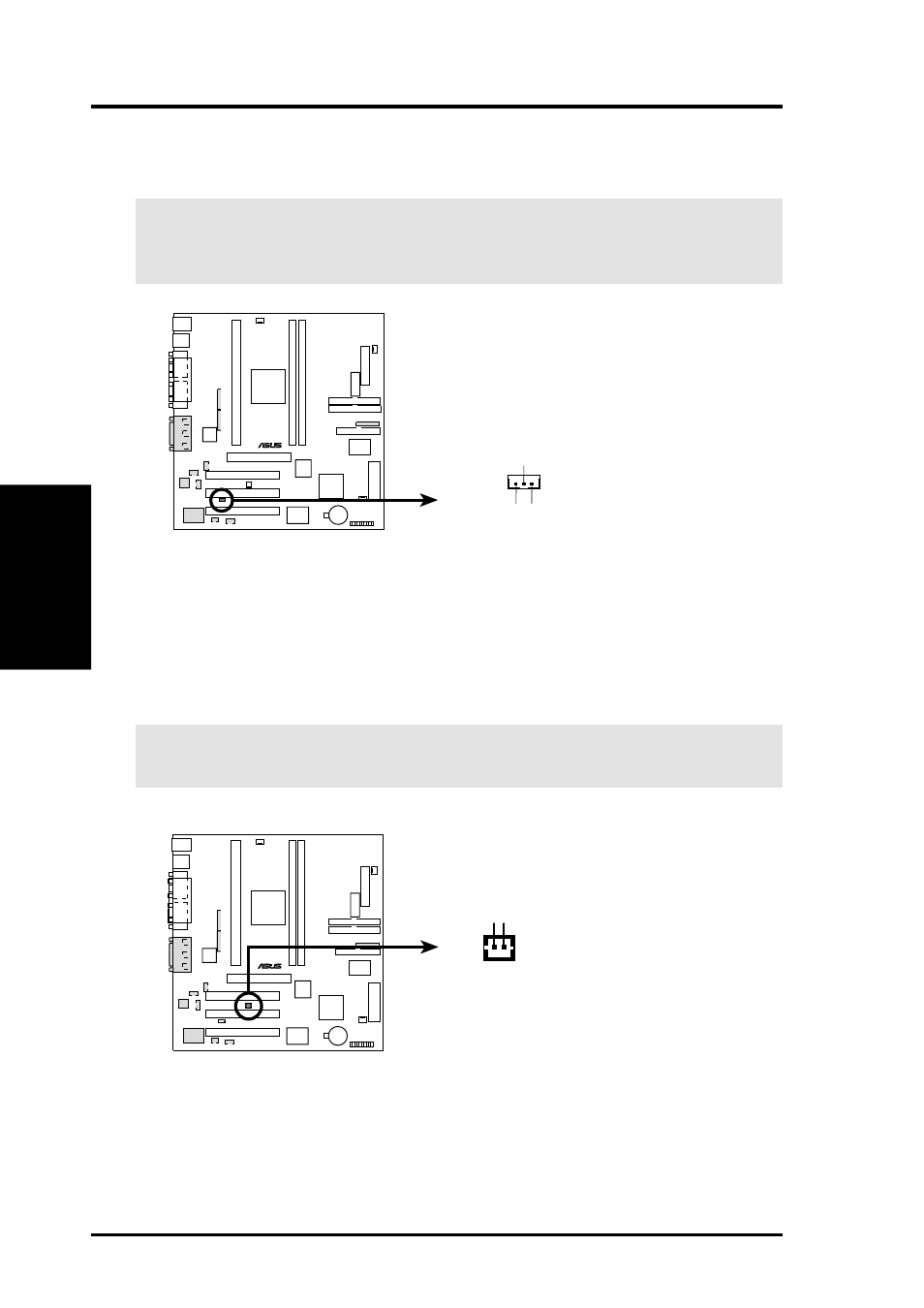
12) Wake-On-LAN Connector (3-pin WOL_CON)
The WOL_CON connector powers up the system when a wake-up packet or
signal is received from the network through the ASUS PCI-L101 LAN card.
IMPORTANT:
This feature requires that Wake On LAN is set to Enabled (see
4.6 Power Management Setup) and that your system has an ATX power supply
with at least 720mA +5V standby power.
P3B-1394
®
P3B-1394 Wake-On-LAN Connector
+5 VSB PME
Ground
WOL_CON
13) Wake-On-Ring Connector (2-pin WOR)
This connector connects to an internal modem card with a Wake-On-Ring out-
put. The connector powers up the system when a ringup packet or signal is re-
ceived through the internal modem card. NOTE: For external modems, Wake-
On-Ring is detected through the COM port.
IMPORTANT:
This feature requires that PWR Up On Modem Act is set to
Enabled (see 4.6 Power Management Setup).
P3B-1394
®
P3B-1394 Wake-On-Ring Connector
WOR
Pin 1 Ground
Pin 2 PIXRI#
- P5B Premium Vista Edition (188 pages)
- P5B (140 pages)
- P5B (56 pages)
- P5KPL-VM/1394/SI (94 pages)
- M2N68-CM (28 pages)
- P5AD2-E Premium (2 pages)
- P5GD1-VM (88 pages)
- P5AD2 Premium (8 pages)
- P5GD1-VM (92 pages)
- DELUXE A7N8X-E (114 pages)
- P5KPL-AM SE (40 pages)
- P5KPL-AM SE (38 pages)
- P5KPL-AM SE (62 pages)
- P4S8X-X (64 pages)
- P5K-VM (98 pages)
- K8V-X SE (82 pages)
- M2N68-AM SE2 (40 pages)
- P4P800 SE (125 pages)
- P4P800 SE (16 pages)
- DELUXE SERIES M3A32-MVP (176 pages)
- P5AD2 Deluxe (148 pages)
- M4A79 Deluxe (122 pages)
- A7V266-E (108 pages)
- Application Manual (8 pages)
- Application Manual (2 pages)
- Application Manual (6 pages)
- Application Manual (9 pages)
- Application Manual (3 pages)
- Application Manual (1 page)
- Application Manual (5 pages)
- Application Manual (11 pages)
- Application Manual (10 pages)
- Application Manual (4 pages)
- M4A88T-I DELUXE (70 pages)
- M4A88T-I DELUXE (44 pages)
- P9X79 DELUXE (2 pages)
- RAMPAGE IV GENE (1 page)
- P9X79 (156 pages)
- P8H61-M PLUS V3 (64 pages)
- A85XM-A (78 pages)
- M4A78L-M LE (64 pages)
- M2N68-AM (62 pages)
- M2N68-AM (38 pages)
- M2N68-AM (96 pages)
- Blitz Formula (1 page)