Hardware setup – Asus P3B-1394 User Manual
Page 38
38
ASUS P3B-1394 User’s Manual
3. HARDWARE SETUP
Connectors
3. H/W SETUP
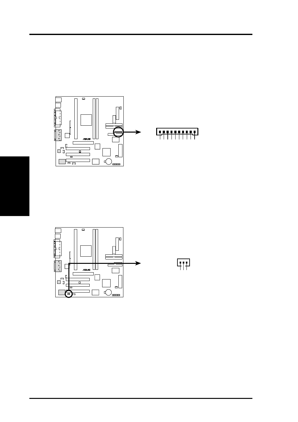
25) Serial Port Header (10-pin COM2)
The optional IEEE-1394 and serial combination cable with bracket can be used
to add an additional serial port for a second serial device. Connect the IEEE-
1394 cables from the 1394 CON board to the two IEEE-1394 headers
(1394HEAD2/1394HEAD3), the serial cable from the bracket to the COM2
header, and then mount the bracket to the chassis on a free expansion slot.
P3B-1394
®
P3B-1394 Serial COM2 Header
COM2
1
10
DSA2#
R
TS2#
DT
A2#
RXD2
DCD2#
TXD2
RI2#
-12V
+5V
CTS2#
26) Digital Audio Interface Header (3-pin SPDIFOUT)
This header is the digital link between the motherboard and your devices, such
as CD player, sampler, or DAT recorder. It allows the digital transmission of
audio data in SPDIF (Sony/Philips Digital Interface) format.
P3B-1394
®
P3B-1394 Audio Digital Interface Connector
SPDIFOUT
+5V
SPDIFOUT
Ground
- P5B Premium Vista Edition (188 pages)
- P5B (140 pages)
- P5B (56 pages)
- P5KPL-VM/1394/SI (94 pages)
- M2N68-CM (28 pages)
- P5GD1-VM (92 pages)
- P5AD2-E Premium (2 pages)
- P5GD1-VM (88 pages)
- P5AD2 Premium (8 pages)
- DELUXE A7N8X-E (114 pages)
- P5KPL-AM SE (62 pages)
- P5KPL-AM SE (40 pages)
- P5KPL-AM SE (38 pages)
- P4S8X-X (64 pages)
- P5K-VM (98 pages)
- K8V-X SE (82 pages)
- M2N68-AM SE2 (40 pages)
- P4P800 SE (16 pages)
- P4P800 SE (125 pages)
- DELUXE SERIES M3A32-MVP (176 pages)
- P5AD2 Deluxe (148 pages)
- M4A79 Deluxe (122 pages)
- A7V266-E (108 pages)
- Application Manual (4 pages)
- Application Manual (8 pages)
- Application Manual (2 pages)
- Application Manual (6 pages)
- Application Manual (9 pages)
- Application Manual (3 pages)
- Application Manual (1 page)
- Application Manual (5 pages)
- Application Manual (11 pages)
- Application Manual (10 pages)
- M4A88T-I DELUXE (44 pages)
- M4A88T-I DELUXE (70 pages)
- P9X79 DELUXE (2 pages)
- RAMPAGE IV GENE (1 page)
- P9X79 (156 pages)
- P8H61-M PLUS V3 (64 pages)
- A85XM-A (78 pages)
- M4A78L-M LE (64 pages)
- M2N68-AM (96 pages)
- M2N68-AM (62 pages)
- M2N68-AM (38 pages)
- Blitz Formula (2 pages)