Hardware setup – Asus P3B-1394 User Manual
Page 37
ASUS P3B-1394 User’s Manual
37
3. HARDWARE SETUP
Connectors
3. H/W SETUP
21) IDE Activity LED Lead (2-pin IDELED)
This 2-pin connector supplies power to the cabinet’s IDE activity LED. Read
and write activity by devices connected to the Primary or Secondary IDE con-
nectors will cause the LED to light up.
22) System Power LED Lead (3-1 pin PLED)
This 3-1 pin connector connects to the system power LED, which lights when
the system is powered ON and turns OFF when it is in sleep or soft-off mode.
23) Reset Switch Lead (2-pin RESET)
This 2-pin connector connects to the case-mounted reset switch for rebooting
your computer without having to turn off your power switch. This is a preferred
method of rebooting to prolong the life of the system’s power supply.
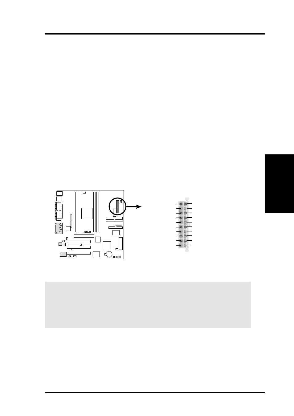
24) ATX Power Supply Connector (20-pin ATXPWR)
This connector connects to an ATX power supply. The plug from the power
supply will only insert in one orientation because of the different hole sizes.
Find the proper orientation and push down firmly but gently making sure that
the pins are aligned.
P3B-1394 ATX Power Connector
+3.3 Volts
-12.0 Volts
Ground
Power Supply On
Ground
Ground
Ground
-5.0 Volts
+5.0 Volts
+5.0 Volts
Power Good
+12.0 Volts
+3.3 Volts
+3.3 Volts
Ground
+5.0 Volts
Ground
+5.0 Volts
Ground
+5V Standby
P3B-1394
®
IMPORTANT:
Make sure that your ATX power supply can supply at least 10mA
on the 5-volt standby lead (5VSB). You may experience difficulty in powering
on your system if your power supply cannot support the load. For Wake-On-
LAN and suspend-to-RAM support, your ATX power supply must supply at
least 720mA +5VSB.