32 chapter 2: hardware information, P5ql-e analog front panel connector, P5ql-e serial port2(com1) connector – Asus P5QL-E User Manual
Page 56
2-32
Chapter 2: Hardware information
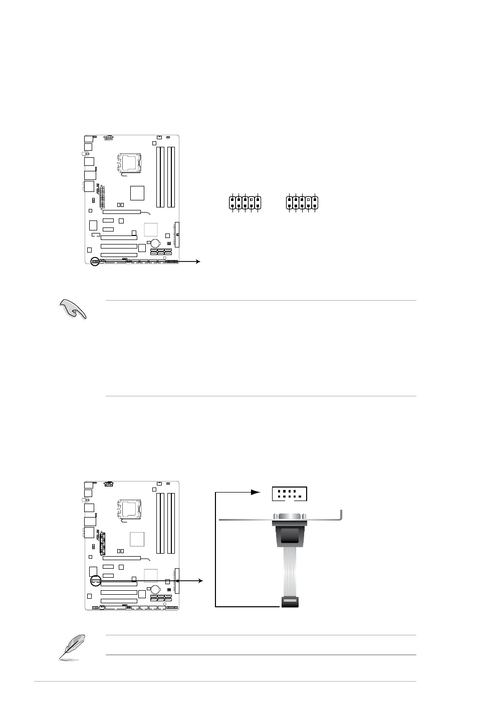
10. Front panel audio connector (10-1 pin AAFP)
This connector is for a chassis-mounted front panel audio I/O module that
supports either HD Audio or legacy AC`97 audio standard. Connect one end
of the front panel audio I/O module cable to this connector.
• We recommend that you connect a high-definition front panel audio
module to this connector to avail of the motherboard’s high-definition audio
capability.
• If you want to connect a high-definition front panel audio module to this
connector, make sure that the Front Panel Type item in the BIOS is set to
[HD Audio]. If you want to connect an AC' 97 front panel audio module to
this connector, set the item to [AC97]. Refer to page 4-27 for details.
P5QL-E
P5QL-E Analog front panel connector
AAFP
PIN 1
GN
D
PRESENCE
#
SENSE1_RETUR
SENSE2_RETUR
PORT1
L
PORT1
R
PORT2
R
SENSE_SEND
PORT1
L
HD-audio-compliant
pin definition
PIN 1
AGND
NC
NC
NC
MIC2
MICPWR
Line out_R
NC
Line out_L
Legacy AC’97
compliant definition
P5QL-E
P5QL-E Serial port2(COM1) connector
PIN 1
COM1
11. Serial port connector (10-1 pin COM1)
This connector is for a serial (COM) port. Connect the serial port module
cable to this connector, then install the module to a slot opening at the back
of the system chassis.
The serial port module cable is purchased separately.