Asus Blitz Extreme User Manual
Page 58
2-32
Chapter 2: Hardware information
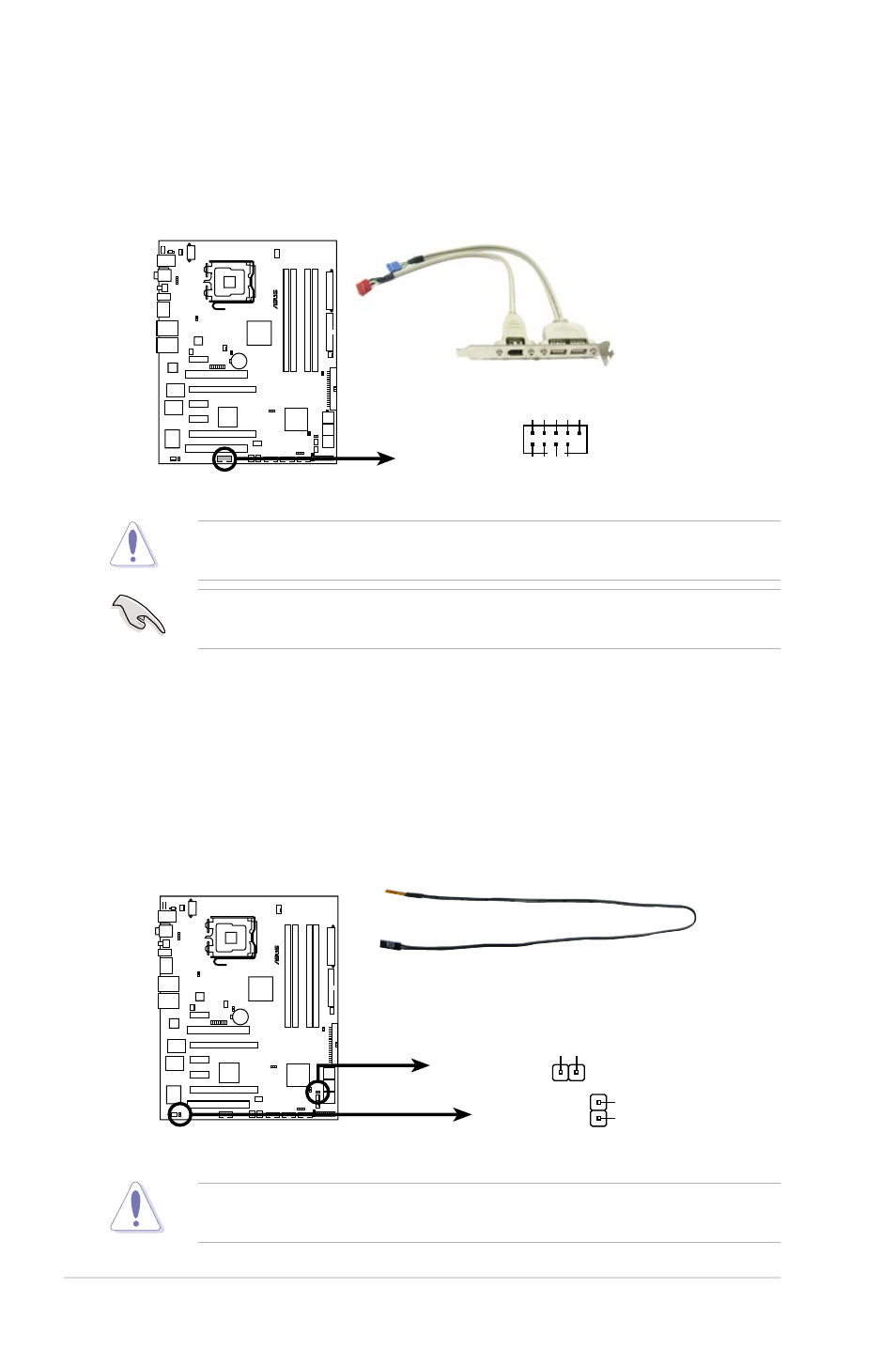
5. IEEE 1394a port connector (10-1 pin IE1394_2)
This connector is for a IEEE 1394a port. Connect the IEEE 1394a module
cable to this connector, then install the module to a slot opening at the back
of the system chassis.
BLITZ EXTREME
®
BLITZ EXTREME IEEE 1394a connector
IE1394_2
PIN 1
GND
+12V
TPB1-
GND
TP
A1-
+12V
TPB1+
GND
TP
A1+
Never connect a USB cable to the IEEE 1394a connector. Doing so will damage
the motherboard!
You can connect the 1394 cable to ASUS Q-Connector (1394, red) first, and
then install the Q-Connector (1394) to the 1394 connector onboard.
6. Thermal sensor cable connectors (2-pin OPT_TEMP1-2)
These connectors are for temperature monitoring. Connect the thermal
sensor cables to these connectors and place the other ends to the devices.
The OPT_TEMP connectors are for the devices that you want to monitor
temperature. The optional fans can work with the temperature sensors for a
better cooling effect.
BLITZ EXTREME
®
BLITZ EXTREME Thermal sensor cable connectors
OPT_TEMP1
Te
mperature
Ground
Temperature
Ground
OPT_TEMP2
Remove the thermal sensor cable from the assigned device when you set this
item to [SB Overheat Protection].