Q-Tech QT802 Square Wave User Manual
Page 5
QT801 and QT802 Square-Wave
24 pin DDIP
REV.
Q-TECH Corporation
10150 W. Jefferson Blvd.
Culver City, CA 90232
SIZE
A
CAGE NO.
51774
Sheet 5 of 10
D
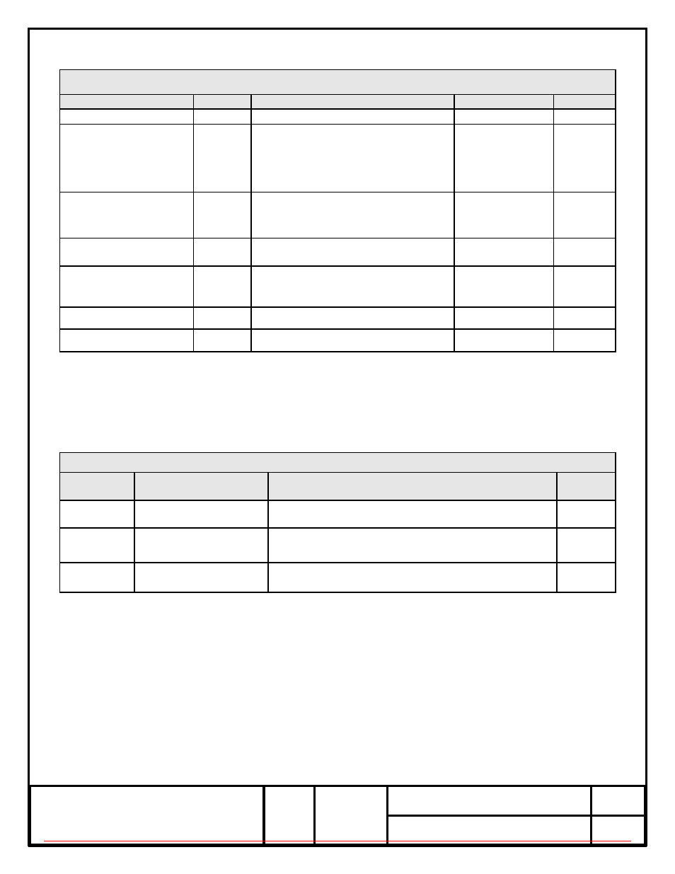
Group A Inspection
PARAMETER
SYMBOL
CONDITIONS
VALUE
UNIT
Input Current, max.
Is
Vs, nom. / Ta=+25°C
50
mA
Freq. stability vs.
temperature
Δf/fc (Ta)
Vs, nominal and over the temperature
range indicated under part number
definition
indicated under
part number
definition
ppm
Electrical Frequency
Adjustment Min.
(when specified)
Δf/fo
(ΔVcc)
± Vs, nom. / Ta=+25°C as indicated
under part number definition
indicated under
part number
definition
ppm
Output
VOH /
VOL
load=15pF, Vcc=nom.
0.9•Vcc / 0.1•Vcc
V
Duty cycle
DC
load=15pF/ @50%Vcc, Ta=+25°C
indicated under
part number
definition
%
Rise- / fall time
tr / tf
20%~80% Vout, 80%~20% Vout
.5…7 (see note A)
nSec
External Visual
MIL-STD-883, Method 2009
A:
Supply Current, rise & fall time are frequency dependent
Group B Inspection
SUB-
GROUP
TEST DESCRIPTION
CONDITION
QTY
1
Frequency Aging
MIL-PRF-55310
Para 3.6.34.2
100%
2
Hermetic Seal 1/
Fine Leak – MIL-STD-883 Method 1014 Condition A1
Gross Leak – MIL-STD-883, Method 1014 Condition C
100%
3
Electrical 1/ (Go/NoGo)
100%
1/ Testing shall be performed after completion of Frequency Aging and before parts are shipped.
ITAR-CONTROLLED Q-TECH PROPRIETARY DO NOT COPY OR DISTRIBUTE WITHOUT Q-TECH APPROVAL