3 ps400 panel layout – SENA PS400 User Manual
Page 13
13
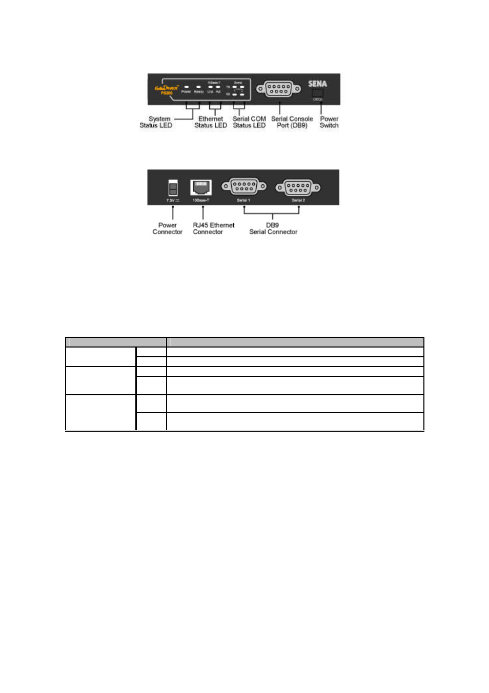
(a) The front panel of the PS200
(b) The rear panel of the PS200
Figure 2-2. The panel layout of the PS200
Table 2-2. LED indicator lamps of the PS200
Lamps
Function
Power
Turned on to RED if power is supplied
System Status
LED
Ready
Turned on to Green if system is running
Link
Turned on to Green if connected to 10 Base-T Ethernet network
Ethernet Status
LED
Act
Blink whenever there is any activities such as incoming or outgoing packets
through the PS200 Ethernet port
Rx
Blink whenever there is any incoming data stream through the specified
serial port of the PS200
Serial port 1~ 2
Status LED
Tx
Blink whenever there is any outgoing data stream through the specified
serial port of the PS200
2.1.3 PS400 Panel Layout
The front panel of the PS400 has one power switch, one DB9 serial port connector and twelve LED
indicator lamps for status display. The lamp on the left-hand side indicates the status of the system
power -on and system ready. Next two lamps indicate statuses of 10 Base-T Ethernet Link and Act.
Eight other lamps indicate statuses of receive and transmit of each serial port. Table 2-3 describes
function of each LED indicator lamp on the panel.
The rear panel of the PS400 has one power connector, one RJ45 Ethernet connector for 10 Base-T
interface and four DB9 connectors for serial interface.