Important: voltage regulation, Pinout diagrams for ocean optics spectrometers – Ocean Optics External Triggering Options User Manual
Page 2
External Triggering Options Instructions
2
200-00000-000-01-201401
Triggering Mode Description
Applicable Spectrometer(s)
Quasi-Real Time
Acquisition
Mode
The integration clock is set to 4ms, which is the time
required to completely read out all the pixels. When the
software (user) requests a spectrum, the integration
clock waits for the current period to expire, changes to
the desired integration time set via software
commands, and then returns to 4ms. With this
approach, the start of the integration period will always
be within 4ms of the time when the request for a
spectrum is issued. No trigger signal is required to
operate in this mode.
QE65000, Maya2000,
Maya2000 Pro
IMPORTANT:
Voltage Regulation
The maximum recommended voltage on the Triggering Pin is 5.5 V. If your triggering device exceeds
this voltage, you must regulate or condition the signal (via transistor buffering, transformer isolation or
opto-isolation, for example) or isolate the signal from the spectrometer.
Note
To use one of the External Triggering options, you must know the specifications and
limitations of the triggering device. The design of the triggering device may prevent you
from using one of the external triggering modes as it is described in these pages.
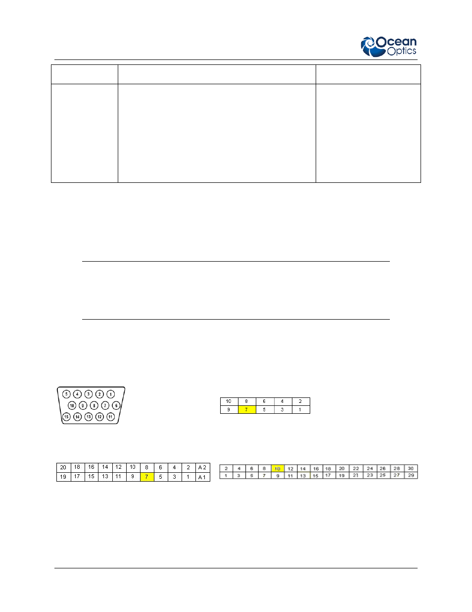
Consult the following images and table for information on which pin to connect to the triggering device
when using each triggering mode on the spectrometer.
Pinout Diagrams for Ocean Optics Spectrometers
J2 (D-SUB-15) Accessory Connector on NIR
Series, S2000 and S1024DW Spectrometers
Pinout Diagram of 10-pin Connector on USB2000
Spectrometer
Pinout Diagram of 22-pin Connector on
USB2000+, USB4000, Jaz and HR2000
Spectrometers (be sure to also use Ground
Pin 6 when triggering)
Pinout Diagram of 30-pin Connector on HR2000+,
HR4000, JazNIRQuest Series, and QE65000
Spectrometers