When to use external hardware trigger mode, Using the external hardware triggering mode, S2000 miniature fiber optic spectrometer – Ocean Optics External Triggering Options User Manual
Page 12
External Triggering Options Instructions
12
200-00000-000-01-201401
When to Use External Hardware Trigger Mode
Use the External Hardware Trigger mode if you:
• Are using a pulsed excitation or light source in your experiment
• Are doing LIF (fluorescence with pulsed excitation) or phosphorescence experiments
• Are able to jumper the pins on Jumper Block 4 of the spectrometer’s electronic board
• Need to synchronize an acquisition with an external event
Using the External Hardware Triggering Mode
► Procedure
Supply a line from Pin 4 of the J2 Accessory Connector to the triggering device. (See figure in
Diagrams for Ocean Optics Spectrometers
1. Connect Pin 10 of the J2 Accessory Connector (ground) to the ground of the triggering
device.
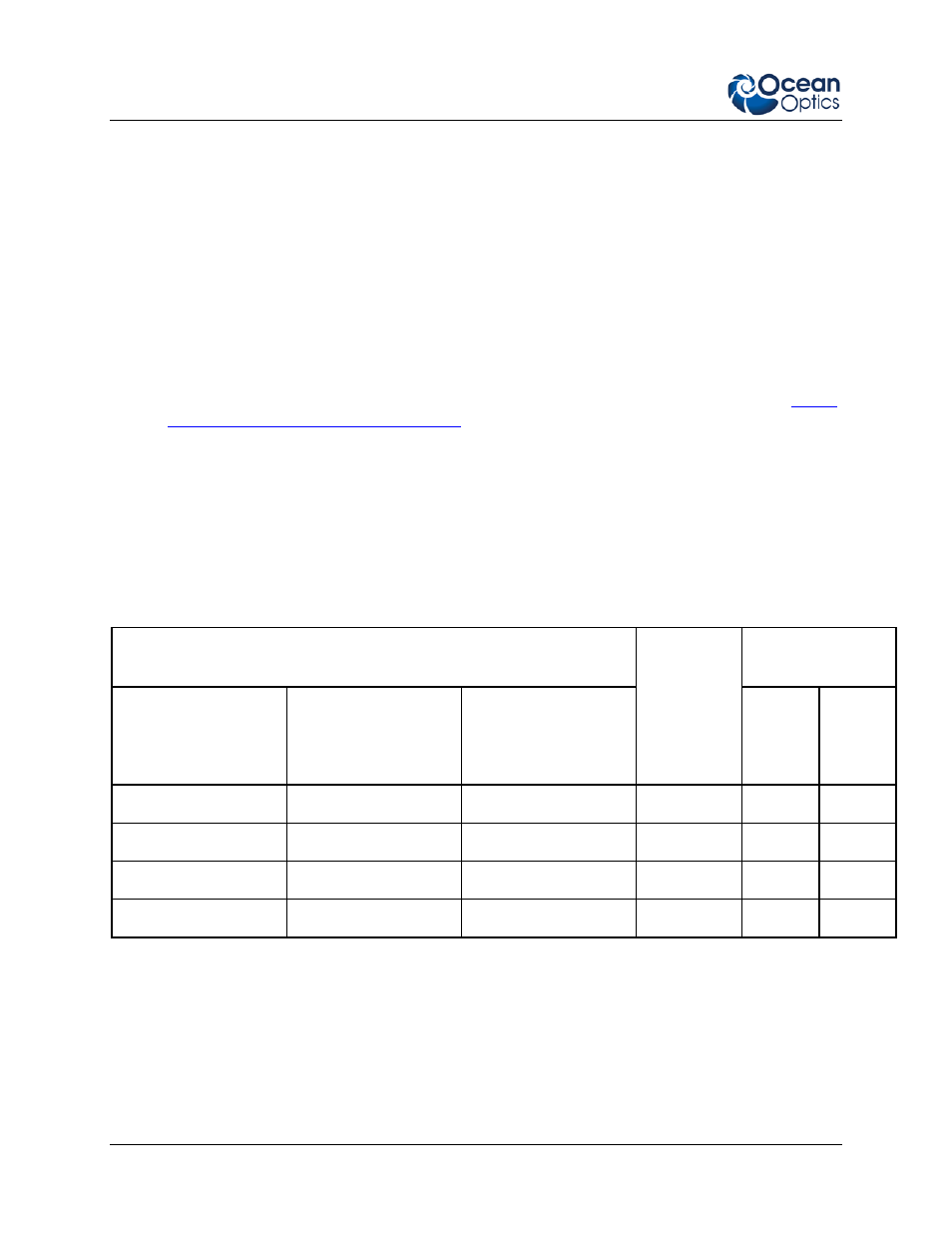
2. Consult the charts below to determine the integration time. Identify the Spectrometer and
A/D converter you are using, and then choose the integration time.
S2000 Miniature Fiber Optic Spectrometer
Integration Time
Integration
Time
Equation
Jumper Block 4
(JP4)
ADC500, SAD500
(500 kHz Master Clock
Freq)
ADC1000
(1 MHz Master Clock
Freq)
ADC2000
(2 MHz Master Clock
Freq)
Pins 1-2 Pins 3-4
8.8 ms
4.4 ms
2.2 ms
8.8/F
m
open
open
27.5 ms
13.3 ms
6.7 ms
27.5/F
m
open
shorted
55 ms
27.5 ms
13.8 ms
55/F
m
shorted
open
137.5 ms
68.8 ms
34.4 ms
137.5/F
m
shorted
shorted
F
m
= the master clock frequency in MHz; shorted = connected; open = disconnected