S1024dw miniature fiber optic spectrometer – Ocean Optics External Triggering Options User Manual
Page 13
External Triggering Instructions
200-00000-000-01-201401
13
S1024DW Miniature Fiber Optic Spectrometer
Integration Time
SAD500
(500 kHz Master Clock
Freq)
Integration Time
Equation
Jumper Block 4 (JP4)
Pins 1-2
Pins 3-4
5 ms
1000/F
m
open
open
60 ms
12000/F
m
open
shorted
300 ms
60000/ F
m
shorted
open
655 ms
131070/ F
m
shorted
shorted
F
m
= the master clock frequency in Hz (i.e., 200 kHz for the SAD500); shorted = connected; open = disconnected
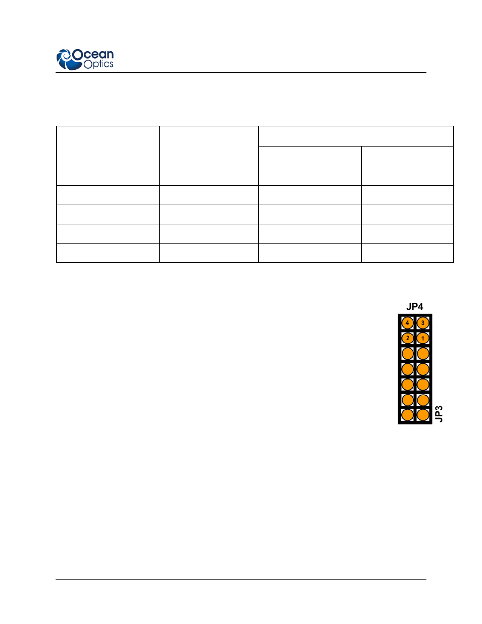
► Procedure
1. Note the configuration of the pins in the Jumper Block 4 column of the chart.
2. Remove the spectrometer from its housing. Do not tamper with the optical bench.
(If you have more than one channel in your system, you may have to disconnect the
channels from one another. The master spectrometer is always on the bottom of a
multiple channel system.)
3. Locate Jumper Block 4 (JP4) in the center of the green circuit board, near the
optical bench. (See the figure to the right.) Jumper Block 4 consists of the first four
pins, which are numbered 1, 2, 3, and 4.
4. Using jumpers, configure the pins to match the integration time you selected.
For example, if you have an S2000 and an ADC1000 A/D Converter, you select
13.3 milliseconds as the integration time. To enable this, place a jumper over pins 3 and 4 to short
the pins, and leave pins 1 and 2 open.
5. Click on the Data Acquisition icon or select Spectrum | Configure Data Acquisition from the
OOIBase32 menu bar, then set other acquisition parameters (averaging, boxcar smoothing, etc.)
in the software.
6. Select the External Trigger page from the Configure Data Acquisition screen, and then select
Hardware Trigger.