Hardware installation – Ocean Optics MultiFrequency Phase Fluorometer User Manual
Page 18
2: Installation
Hardware Installation
WARNING
Ensure that the red plastic caps are covering the four SMA connectors on the front of the
MFPF unit. Intense UV radiation is emitted from the LEDS when the unit is powered-up.
Do NOT look directly at the LED output with the naked eye.
► Procedure
1. Unpack the equipment and verify that you have all the necessary components (see
Additional Recommended Equipment
2. Connect thermistor(s) to T1 and T2 (for Model MFPF100-2) connectors on front of unit.
3. Locate the 21-02 SMA Splice Bushing that came with the probe. This item is a 0.75" screw with
two female ends. Screw one end of the splice bushing into the SMA 905 connector on the end of
the probe.
4. Locate the bifurcated fiber that came with the system. This optical fiber assembly has a “Y”
shaped design. Connect the common end of the bifurcated fiber to the splice bushing/probe.
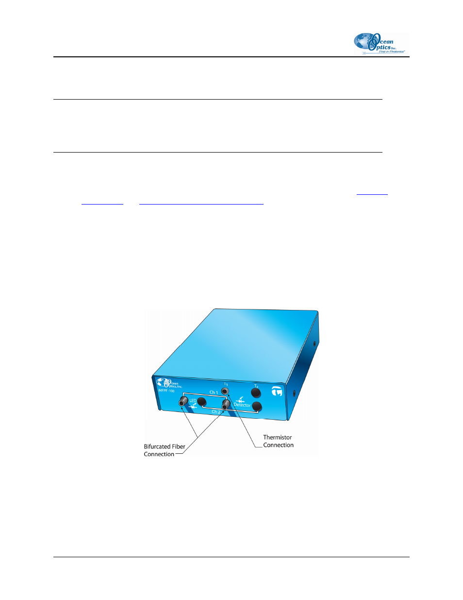
5. Connect one arm (it doesn’t matter which one) of the bifurcated probe fiber to Ch1 LED and the
other arm to the Ch1 Detector on front of unit as shown below.
MFPF Unit Front Panel
6. Connect power cord from the power supply that came with your MFPF unit from back of unit to
an AC outlet. To check that the unit is receiving power, look for light glowing through the LED
#1 red cap, or place a piece of white paper in front of the LED if the red cap is not available. Do
NOT look directly at the light being emitted with the naked eye.
10
MFPF-00000-000-02-1207