Tvs diode arrays, Low capacitance esd protection - sp3012 series, Diodes) – Littelfuse SP3012 Series User Manual
Page 7: Sp30 1 2
7
©2013 Littelfuse, Inc.
Specifications are subject to change without notice.
TVS Diode Arrays
(SPA
®
Diodes)
Revision: 09 2, 13
SP3012 Series
SP30
1
2
Low Capacitance ESD Protection - SP3012 Series
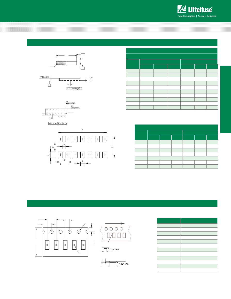
Package Dimensions — µDFN-14 (3.5x1.35x0.5mm)
µDFN-14
(3.5x1.35x0.5mm)
JEDEC MO-229
Symbol
Millimeters
Inches
Min
Nom
Max
Min
Nom
Max
A
0.45
0.50
0.55
0.018
0.020
0.022
A1
0.00
0.02
0.05
0.000
0.001
0.002
A2
0.203 Ref
0.008 Ref
b
0.15
0.20
0.25
0.006
0.008
0.012
D
3.40
3.50
3.60
0.134
0.138
0.142
D2
-
-
-
-
-
-
E
1.25
1.35
1.45
0.050
0.054
0.058
E1
-
-
-
-
-
-
e
0.500 BSC
0.020 BSC
L
0.25
0.30
0.35
0.010
0.012
0.014
D
E
B
Top View
A
Bottom View
Side View
PIN 1 Index Area
1 2 3 4
A
C
b
A1 A2
Seating
Plane
Pin 1 Identification
Chamfer 0.10X45º
Notes:
1. Dimension and tolerancing comform to ASME Y14.5M-1994.
2. Controlling dimensions: Millimeter. Converted Inch dimensions are not necessarily
exact.
Soldering Pad Layout
Recomended
Symbol
Millimeter
Inches
Soldering Pad Layout Dimensions
Symbol
Millimeters
Inches
Min
Nom
Max
Min
Nom
Max
D
3.29
3.30
3.31
0.1295
0.1299
0.1303
E
1.44
1.45
1.46
0.0567
0.0571
0.0575
b
0.29
0.30
0.31
0.0114
0.0118
0.0122
L
0.39
0.40
0.41
0.0154
0.0158
0.0161
e
0.50 typ
0.020 typ
s
0.19
0.20
0.21
0.0075
0.0078
0.0083
s1
0.64
0.65
0.66
0.0252
0.0256
0.0260
Embossed Carrier Tape & Reel Specification — µDFN-14
Symbol
Millimeters
A0
1.58 +/- 0.10
B0
3.73 +/- 0.10
D0
0.60 + 0.05
D1
Ø 0.60 + 0.05
E
1.75 +/- 0.10
F
5.50 +/- 0.05
K0
0.68 +/- 0.10
P0
2.00 +/- 0.05
P1
4.00 +/- 0.10
P2
4.00 +/- 0.10
T
0.28 +/- 0.02
W
12.00 + 0.30 /- 0.10
P0
D0
E
F
P1
P2
D1
W
T
B0
K0
A0
User Feeding Direction
Pin 1 Location