Teccor, Brand thyristors, 40 amp alternistor (high commutation) triacs – Littelfuse Qxx40xx Series User Manual
Page 3
163
Revised: 09/23/13
©2013 Littelfuse, Inc
Specifications are subject to change without notice.
Teccor
®
brand Thyristors
40 Amp Alternistor (High Commutation) Triacs
Qxx40xx Series
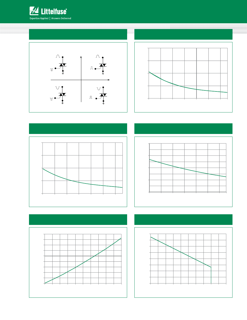
Figure 1: Definition of Quadrants
Figure 3: Normalized DC Holding Current
vs. Junction Temperature
Figure 2: Normalized DC Gate Trigger Current for
All Quadrants vs. Junction Temperature
Figure 4: Normalized DC Gate Trigger Voltage for
All Quadrants vs. Junction Temperature
+125
0.0
1.0
2.0
3.0
4.0
-40 -15 10 35 60 85 110
Junction Temperature -- (°C)
Ratio of I
GT
/ I
GT
(T
J
= 2
5
°C)
+ 125
0.0
1.0
2.0
3.0
4.0
-40 -15 10 35 60 85 110
Ratio of
I
IH
/ I
IH
(T
J
= 2
5
°C
)
Junction Temperature - °C
+125
0.0
0.5
1.0
1.5
2.0
-40- 15 10 35 60 85 110
Ratio of
V
GT
/ V
GT
(T
J
= 2
5
°C)
Junction Temperature - °C
MT2 POSITIVE
(Positive Half Cycle)
MT2 NEGATIVE
(Negative Half Cycle)
MT1
MT2
+
I
GT
REF
QII
MT1
I
GT
GATE
MT2
REF
MT1
MT2
REF
MT1
MT2
REF
QI
QIV
QIII
ALL POLARITIES ARE REFERENCED TO MT1
(
-
)
I
GT
GATE
(+)
I
GT
-
I
GT
GATE
(
-
)
I
GT
GATE
(+)
+
-
Note: Alternistors will not operate in QIV
0
5
10
15
20
25
30
35
40
45
0 4 8 12 16 20 24 28 32 36 40
RMS On-State Current [I
T(RMS)
] - AMPS
Average On-State Power Dissipation
[P
D (AV)
] - Watts
Figure 5: Power Dissipation (Typical)
vs. RMS On-State Current
Figure 6: Maximum Allowable Case Temperature
vs. On-State Current
50
60
70
80
90
100
110
120
130
0 5 10 15 20 25 30 35 40 45 50
RMS On-State Current [I
T(RMS)
] - AMPS
Max Allowable Case Temperature
(T
C
) - ºC