Sidactor, Protection thyristors, Baseband protection (voice-ds1) – Littelfuse SIDACtor Series DO-15 User Manual
Page 3: X l rp, Xxx 0 g
SIDACtor
®
Protection Thyristors
Revised: 01/10/14
© 2014 Littelfuse, Inc.
Specifications are subject to change without notice.
Baseband Protection (Voice-DS1)
SIDACtor
®
Series, DO-15
Physical Specifications
Environmental Specifications
Lead Material
Copper Alloy
Terminal Finish
100% Matte-Tin Plated
Body Material
UL recognized epoxy meeting flammability
classification 94V-0
High Temp Voltage
Blocking
80% Rated V
DRM
(V
AC
Peak
) +125°C or +150°C,
504 or 1008 hrs. MIL-STD-750 (Method 1040)
JEDEC, JESD22-A-101
Temp Cycling
-65°C to +150°C, 15 min. dwell, 10 up to 100
cycles. MIL-STD-750 (Method 1051) EIA/JEDEC,
JESD22-A104
Biased Temp &
Humidity
52 V
DC
(+85°C) 85%RH, 504 up to 1008 hrs. EIA/
JEDEC, JESD22-A-101
High Temp Storage
+150°C 1008 hrs. MIL-STD-750 (Method 1031)
JEDEC, JESD22-A-101
Low Temp Storage
-65°C, 1008 hrs.
Thermal Shock
0°C to +100°C, 5 min. dwell, 10 sec. transfer,
10 cycles. MIL-STD-750 (Method 1056) JEDEC,
JESD22-A-106
Autoclave (Pressure
Cooker Test)
+121°C, 100%RH, 2atm, 24 up to 168 hrs. EIA/
JEDEC, JESD22-A-102
Resistance to Solder
Heat
+260°C, 30 secs. MIL-STD-750 (Method 2031)
Moisture Sensitivity
Level
85%RH, +85°C, 168 hrs., 3 reflow cycles
(+260°C Peak). JEDEC-J-STD-020, Level 1
Part Marking
Part Numbering
CONSTRUCTION
VARIABLE
REEL PACK
I
PP
RATING
RoHS COMPLIANT
TYPE
P = SIDACtor
P
x L RP
MEDIAN VOLTAGE
PACKAGE TYPE
xxx 0 G
Pxxxx
Part Marking Code
(Refer to Electrical Characteristics Table)
XXXXX
Date Code
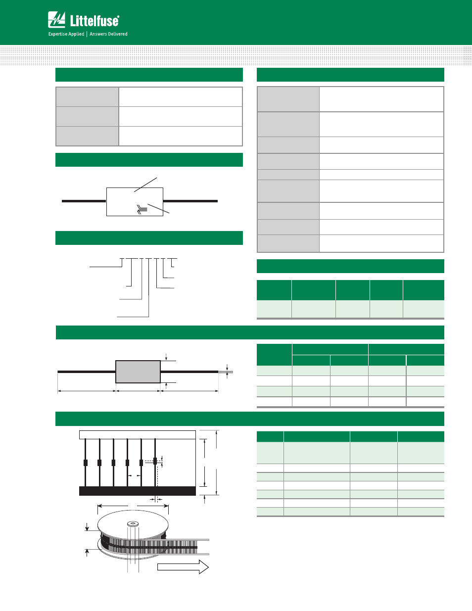
Dimensions — DO-15
Dimensions - DO-15
L
L
G
D
B
(Revised 11/14/07)
Dimension
Inches
Millimeters
MIN
MAX
MIN
MAX
B
0.028
0.034
0.711
0.864
D
0.12
0.14
3.048
3.556
G
0.235
0.27
5.969
6.858
L
1
25.4
Packing Options
Package
Type
Description
Quantity
Added
Suffix
Industry
Standard
G
DO-15 Axial
Tape & Reel
5000
RP
EIA-RS-
296-D
Tape and Reel Specification — DO-15
Spacing
off center,
either side
0.039 (1.0)
B
C
A
D
E
recess depth max 0.75”
2.55
(64.8)
TYP
3.15
(80.0)
TYP
Dimensions
are in inches
(and millimeters).
Direction of Feed
G
F
Symbols
Description
Inches
MM
A
Component Spacing
(lead to lead)
0.200 ± 0.020”
5.08 ± 0.508
B
Inner Tape Pitch
2.062 ± 0.059” 52.37 ± 1.498
C
Tape Width
0.250”
6.35
D
Max. Off Alignment
0.048”
1.219
E
Reel Dimension
13”
330.2
F
Max. Hub Recess
3”
76.19
G
Max. Abor Hole
0.68”
17.27