Teccor, Brand thyristors, Figure 1: definition of quadrants – Littelfuse Qxx10xHx Series User Manual
Page 4
100
Revised: 09/23/13
©2013 Littelfuse, Inc
Specifications are subject to change without notice.
Teccor
®
brand Thyristors
10 Amp Standard & Alternistor (High Communitation) Triacs
Qxx10xx & Qxx10xHx Series
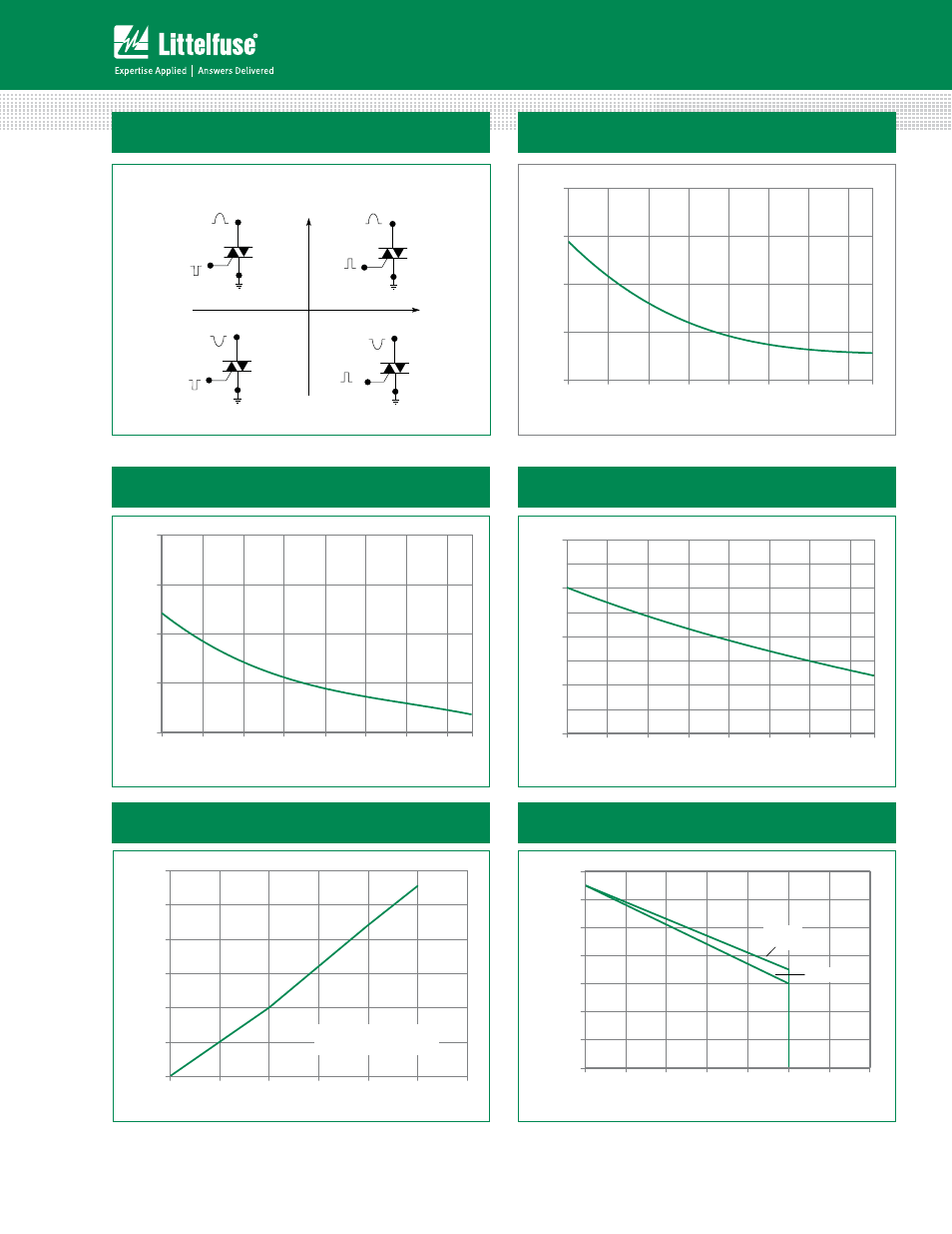
Figure 2: Normalized DC Gate Trigger Current for
All Quadrants vs. Junction Temperature
+125
0.0
1.0
2.0
3.0
4.0
-65 -40 -15 10 35 60 85 110
Junction Temperature (T
J
) - ºC
Ratio of
I
GT
/ I
GT
(T
J
= 2
5
ºC)
MT2 POSITIVE
(Positive Half Cycle)
MT2 NEGATIVE
(Negative Half Cycle)
MT1
MT2
+
I
GT
REF
QII
MT1
I
GT
GATE
MT2
REF
MT1
MT2
REF
MT1
MT2
REF
QI
QIV
QIII
ALL POLARITIES ARE REFERENCED TO MT1
(
-
)
I
GT
GATE
(+)
I
GT
-
I
GT
GATE
(
-
)
I
GT
GATE
(+)
+
-
Figure 1: Definition of Quadrants
Note: Alternistors will not operate in QIV
0
2
4
6
8
10
12
0 2 4 6 8 10 12
RMS On-State Current [I
T(RMS)
] - AMPS
Average On-State Power Dissipation
o
[P
D (AV)
] - Watts
CURRENT WAVEFORM: Sinusoidal
LOAD: Resistive or Inductive
CONDUCTION ANGLE: 360
Figure 5: Power Dissipation (Typical)
vs. RMS On-State Current
Figure 6: Maximum Allowable Case Temperature
vs. On-State Current
Qxx10Ryy
Qxx10Nyy
Qxx10Lyy
60
70
80
90
100
110
120
130
0 2 4 6 8 10 12 14
M
a
x
Allo
w
a
b
le
C
ase T
e
m
p
er
at
u
re
(T
C
) - C
RMS On-State Current [I
T(RMS)
] - AMPS
Figure 3: Normalized DC Holding Current
vs. Junction Temperature
Figure 4: Normalized DC Gate Trigger Voltage for
All Quadrants vs. Junction Temperature
+125
0.0
1.0
2.0
3.0
4.0
-65 -40 -15 10 35 60 85 110
Junction Temperature (T
J
) - ºC
Ratio of
I
H
/ I
H
(T
J
= 2
5
ºC)
+125
0.0
0.5
1.0
1.5
2.0
-65 -40 -15 10 35 60 85 110
Junction Temperature (T
J
) - ºC
Ratio of V
GT
/ V
GT
(T
J
= 2
5
ºC)