Poly-fuse, Resettable ptcs, Radial leaded > 250r series – Littelfuse 250R Series User Manual
Page 7: Figure 1, 250r s eries, Tape and ammo specifications, Tape and ammo diagram a b a, Fl w, Wreference plane δh δh h, Δh δp
103
Revised: August 31, 2011
POLY-FUSE
®
Resettable PTCs
© 2011 Littelfuse, Inc
250R Series
Radial Leaded > 250R Series
Specifications are subject to change without notice.
Please refer to www.littelfuse.com/series/250R.html for current information.
250R S
eries
Dimension
EIA Mark
IEC Mark
Dimensions
Dim. (mm)
Tol. (mm)
Carrier tape width
W
W
18
o
)PMEEPXOUBQFXJEUI
W
4
W
0
11
min.
Top distance between tape edges
W
6
W
2
3
NBY
Sprocket hole position
W
5
W
1
9
o
4QSPDLFUIPMFEJBNFUFS
D
0
D
0
4
o
Abscissa to plane (straight lead)
H
H
18.5
o
Abscissa to plane (kinked lead)
H
0
H
0
16
o
Abscissa to top
H
1
H
1
32.2
NBY
Overall width without lead protrusion
C
1
42.5
NBY
Overall width with lead protrusion
C
2
43.2
NBY
-FBEQSPUSVTJPO
L
1
l
1
1.0
NBY
Protrusion of cut out
L
L
11
NBY
1SPUSVTJPOCFZPOEIPMEoEPXOUBQF
l
2
l
2
Not specified
4QSPDLFUIPMFQJUDI3o3
P
0
P
0
12.7
o
4QSPDLFUIPMFQJUDI3
P
0
P
0
25.4
o
Pitch tolerance
20
consecutive.
o
%FWJDFQJUDI3o3
12.7
%FWJDFQJUDI3
25.4
Tape thickness
t
t
0.9
NBY
Tape thickness with splice
t
1
2.0
NBY
Splice sprocket hole alignment
0
o
Body lateral deviation
Δh
Δh
0
o
Body tape plane deviation
Δp
Δp
0
o
0SEJOBUFUPBEKBDFOUDPNQPOFOUMFBE
P
1
P
1
3.81
o
-FBETQBDJOH
F
F
5.1
o
%JGGFSTGSPN&*"4QFDJGJDBUJPO
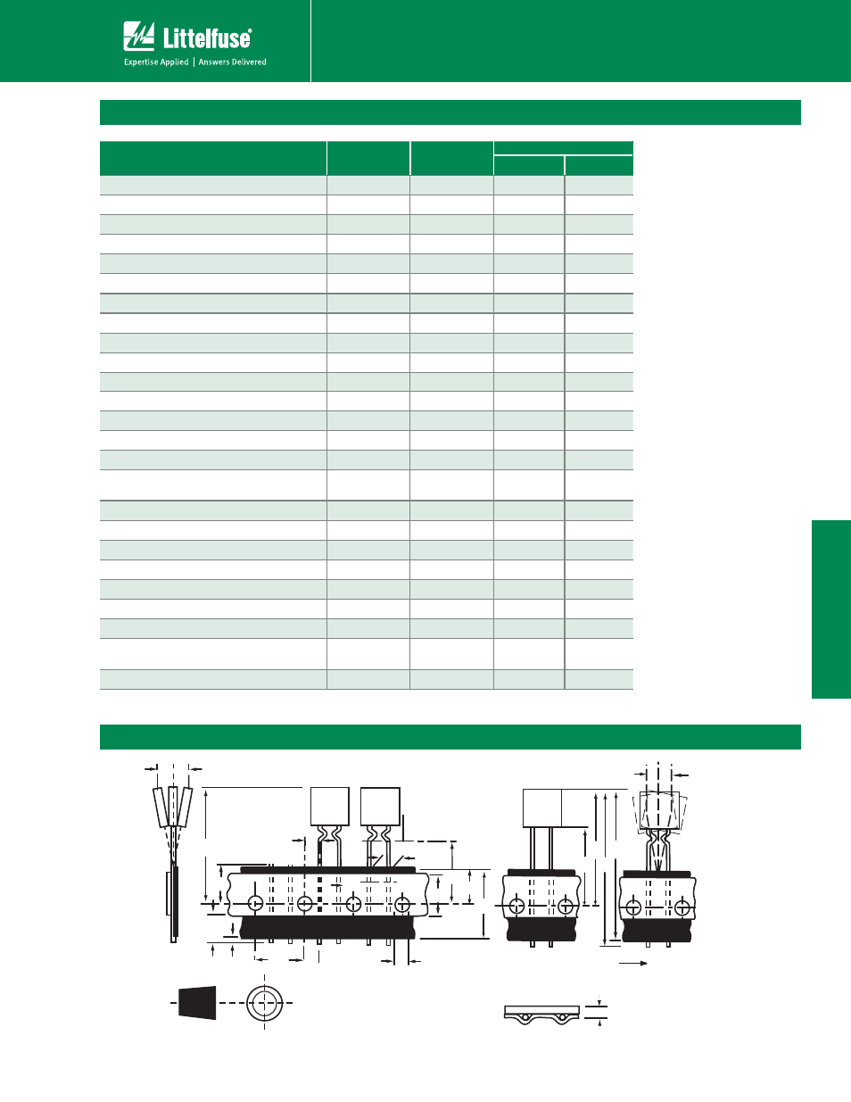
Tape and Ammo Specifications
Devices taped using EIA468-B/IE286-2 standards. See table below and Figure 1 for details.
Tape and Ammo Diagram
A
B
A
1
L
1
P
0
D
0
F
L
W
4
H
0
I
2
H
1
W
5
W
Reference plane
Δh
Δh
H
1
H
C
1
C
2
Δh
Δp
Direction of unreeling
Cross section A - B
t
Figure 1