Teccor, Brand thyristors, Figure 8: diac v – Littelfuse QxxxxLTx Series User Manual
Page 5: Change vs. junction temperature
173
Revised: 09/23/13
©2013 Littelfuse, Inc
Specifications are subject to change without notice.
Teccor
®
brand Thyristors
4 / 6 / 8 / 10 / 15 Amp Quadracs
QxxxxLTx Series
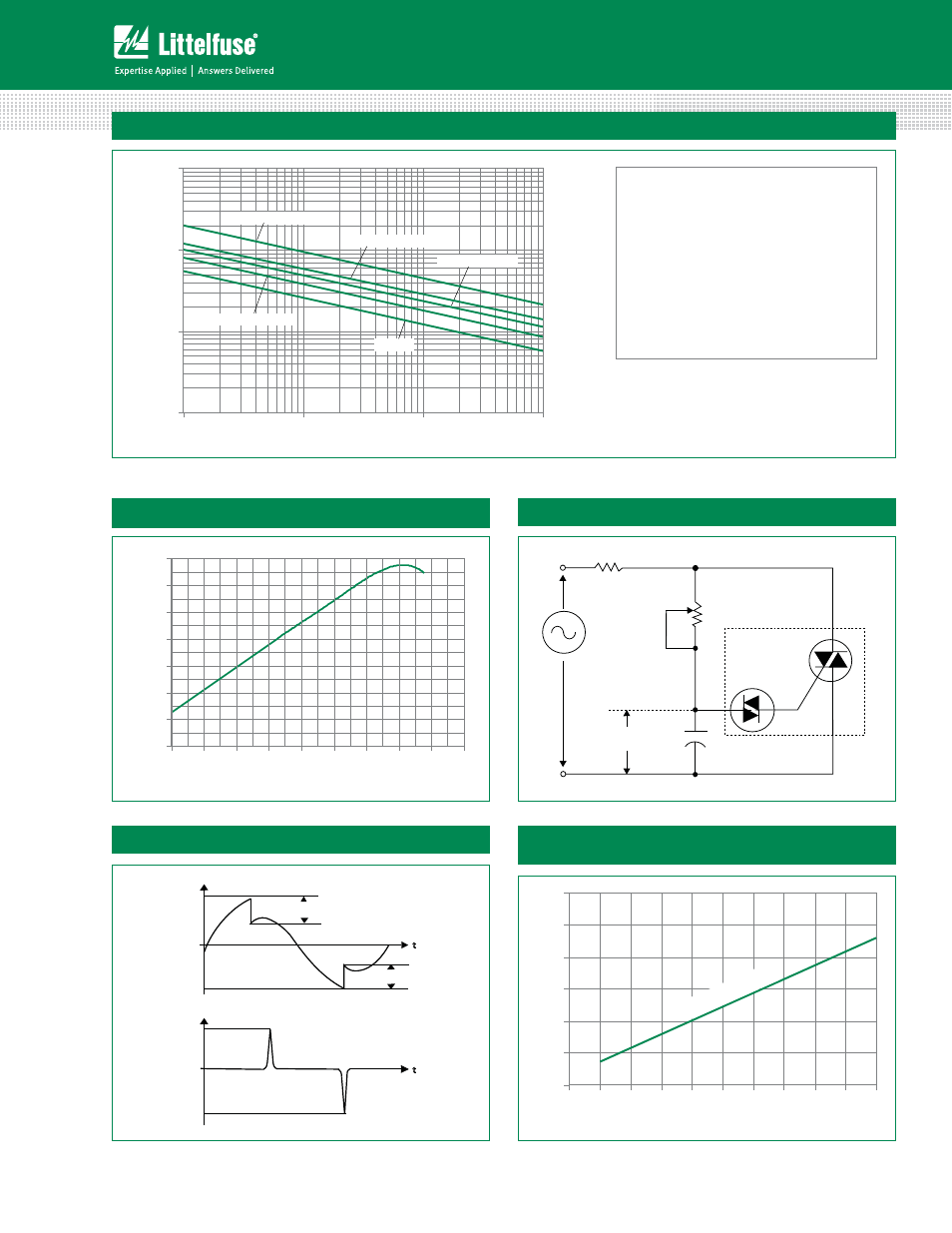
Figure 7: Surge Peak On-State Current vs. Number of Cycles
Note: xx = voltage
1
10
100
1000
1
10
100
1000
Surge Current Duration -- Full Cycles
Peak Surge (Non-repetitive)
On-state Current (I
TSM
) – Amps
Qxx15LT/Qxx15LTH
Qxx04LT
Qxx10LT/Qxx10LTH
Qxx08LT/Qxx08LTH
Qxx06LT/Qxx06LTH
Supply Frequency: 60Hz Sinusoidal
Load: Resistive
RMS On-State Current: [I
T(RMS)
]: Maximum Rated
Value at Specific Case Temperature
Notes:
1. Gate control may be lost during and immediately
following surge current interval.
2. Overload may not be repeated until junction
temperature has returned to steady-state
rated value.
-8%
-6%
-4%
-2%
0%
2%
4%
6%
-40
-20
0
20
40
60
80
100
120
140
Junction Temperature (T
J
) -- °C
V
BO
C
h
a
nge
-
- %
Figure 8: DIAC V
BO
Change vs. Junction Temperature
D.U.T.
MT2
MT1
C
T
= 0.1
μF
T
V
C
120 V
60 Hz
R
L
ΔV+
ΔV-
V
C
+V
BO
-V
BO
0
I
L
+I
PK
-I
PK
0
t
t
Typical pulse base width is 10μs
Figure 9: Test Circuit
Figure 10: Test Circuit Waveform
0
50
100
150
200
250
300
0.1
0.2
0.3
0.4
0.5
0.6
0.7
0.8
0.9
1.0
Triggering Capacitance (C
T
) – μF
Peak Output Current (I
PK
) – mA
Typical (3
5V Device)
Figure 11: Peak Output Current vs Triggering
Capacitance (Per Figure 9)