Teccor, Brand thyristors, 8 amp sensitive & standard triacs – Littelfuse QxXx Series User Manual
Page 4
20
Revised: 09/23/13
©2013 Littelfuse, Inc
Specifications are subject to change without notice.
Teccor
®
brand Thyristors
0.8 Amp Sensitive & Standard Triacs
LxX8Ex & LxXx & QxX8Ex & QxXx Series
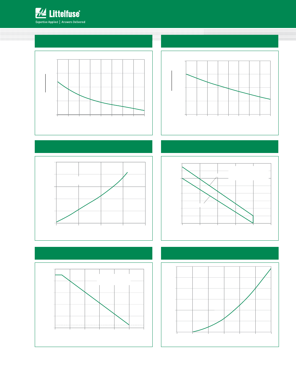
Figure 3: Normalized DC Holding Current
vs. Junction Temperature
Junction Temperature (T
J
)- ºC
Ratio of
I
H
I
H
(T
J
= 2
5
°C)
110
125
85
60
35
10
-15
-40
-65
4.0
0.0
1.0
2.0
3.0
Figure 4: Normalized DC Gate Trigger Voltage for
All Quadrants vs. Junction Temperature
Junction Temperature (T
J
)- ºC
Ratio of
V
GT
V
GT
(T
J
= 2
5
°C)
110
125
85
60
35
10
-15
-40
-65
4.0
0.0
1.0
2.0
3.0
RMS On-State Current (I
T(RMS)
) - Amps
1
0.75
0.5
0.25
0
0
A
v
er
ag
e On-Stat
e
P
o
w
er Dissipation (P
D(A
V)
) -
W
a
tt
s
0.3
0.5
0.8
1.0
1.3
CURRENT WAVE FORM: Sinusoidal
LOAD: Resistive or Inductive
CONDUCTION ANGLE: 360°
Figure 5: Power Dissipation (Typical)
vs. RMS On-State Current
Figure 6: Maximum Allowable Case Temperature
vs. On-State Current
RMS On-State Current (I
T(RMS)
) - Amps
1.0
0.8
0.6
0.4
0.2
0
50
Maximum Allo
w
able
Case T
emper
at
ur
e
(T
C
) - °C
60
70
80
90
100
110
120
130
LxX8Ex / LxXx
QxX8Ex / QxXx
CURRENT WAVE FORM: Sinusoidal
LOAD: Resistive or Inductive
CONDUCTION ANGLE: 360°
CASE TEMPERATURE: Measured as
shown on Dimensional Drawing
Figure 8: On-State Current vs. On-State Voltage
(Typical)
On-State Voltage (V
T
) - Volts
1.8
1.6
1.4
1.2
1.0
0.8
0.6
0
On-Stat
e Cur
rent (I
T
) -
Amps
T
J
= 25°C
1
2
3
4
5
6
Figure 7: Maximum Allowable Ambient Temperature
vs. On-State Current
RMS On-State Current (I
T(RMS)
) - Amps
0.6
0.5
0.4
0.3
0.2
0.1
0.0
120
100
80
60
40
20
Maximum Allowable
Ambient Temperature (T
A
) - °C
CURRENT WAVEFORM: Sinusoidal
LOAD: Resistive or Inductive
CONDUCTION ANGLE: 360°
FREE AIR RATING – NO HEATSINK